
Baseboards for Hall Royd
In the beginning there was...a cardboard mock-up.
Looking at the prototype and using a mix of town planning maps helpfully provided by Calderdale Council on their Website and Google Earth screen grabs, I reckoned that the prototype track layout from the top of Millwood Tunnel to beyond Hall Royd bridge (where the Copy Pit line peels away) could be neatly broken into three 4 foot sections.
Model Railway Solutions in Bournemouth offer baseboard kits on eBay so I used 3 of their 4'x2' kits. These do make up into a very strong and lightweight design - important for me as the layout would normally live in the loft, but I wanted to be able to bring down boards into 'day light' to work on sections in the comfort of my own sitting room.
These are made with a 12mm good plywood frame and 6mm plywood cross braces, and have a 100mm deep frame (approximately 4"). The lightening holes both help reduce weight whilst maintaining strength and rigidity, and also facilitate the wiriing runs.
MRS say there are simple, easy to follow instructions included - which they are. Just be aware that the sections are handed, and that the spine down the middle is off-centre.
It's worth making sure that the top surface of the finished boards is distinctively marked in some way, as post-assembly I put the embryonic layout together with one of the boards inverted, and didn't realise my mistake until AFTER I had altered the inter-baseboard connectors!
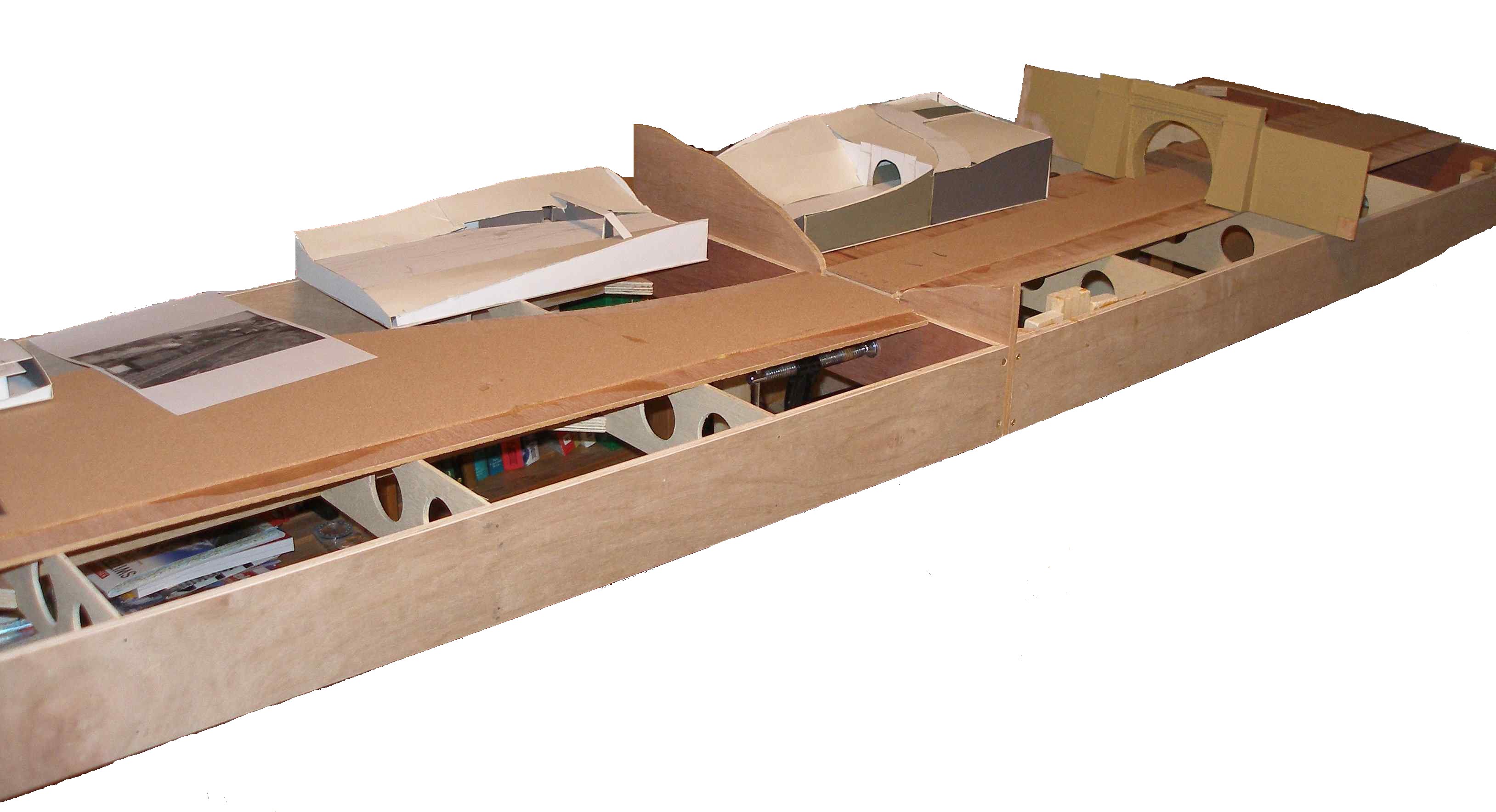
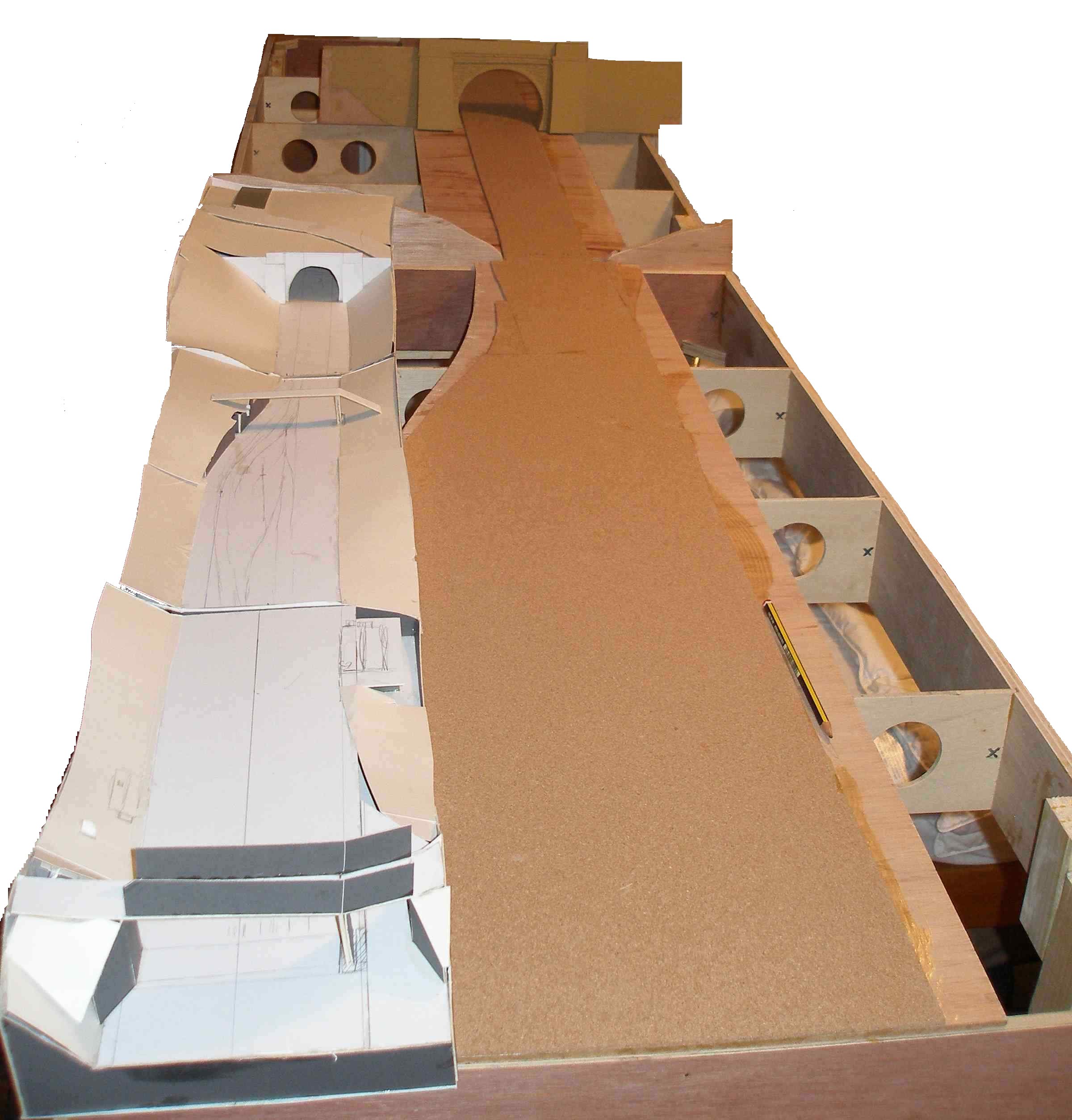
Note the cardboard model laid on top of the baseboard.
The only other small issue is that the ends have bowed slightly in the horizontal plain, and I have put a third set of clips between the boards underneath. This draws the two baseboards together and closes up the gaps in the rails neatly. I suspect that I probably needed a full width baseboard top at the baseboard ends to give them the necersary rigidity.
The scenery veneers were then cut and affixed to the top of the side bearers, and this has worked as intended.
Click here to read about the construction of a sub-frame to allow the boards to be easily rotated to allow work on the undersides.
Copyright J K Wallace, t/a 'Hall Royd Junction' 2013-2023 email: Hall Royd Junction
7 Portobello Close, Chesham, Bucks. HP5 2PL, UK
tel: +44 (0)7513 412880