
Point Rodding
If you have points, you will need point rodding, even if it is a short run from the tie-bar to a solitary lever.
For Hall Royd I have initially used the Wills Rodding Sets SS0089 and SS0090. This is nicely molded and has some useful bits and pieces. I chose it because I wanted something I could deploy quickly.
From my initial limited experience with it, I would say it is intended for layouts that use Peco track with the moulded underlay, as it is a tad over scale. This means it works best for relatively 'simple' rodding layouts; say 5 or 6 levers. This view is supported by the fact that only two compensators are supplied in each set of cranks. In the event I should have bought a larger number of the SS89 pack (which contains rodding) and fewer of the SS90 pack.
Other systems are available, and there is a nice write-up and comparison on Geoff Forster's beautiful Llangunllo layout blog.
Geoff has used the 3D printed GWR / Blackall's anti-friction rollers from Modelu, through which is threaded appropriate round or square bar from Eileen's Emporium. This is near to scale proportions and is consequently more compact. This maty explain why the Wills is a very tight fit under the footbridge, but the Modelu variety fits very neatly. At some point I expect to revisit the point rodding.
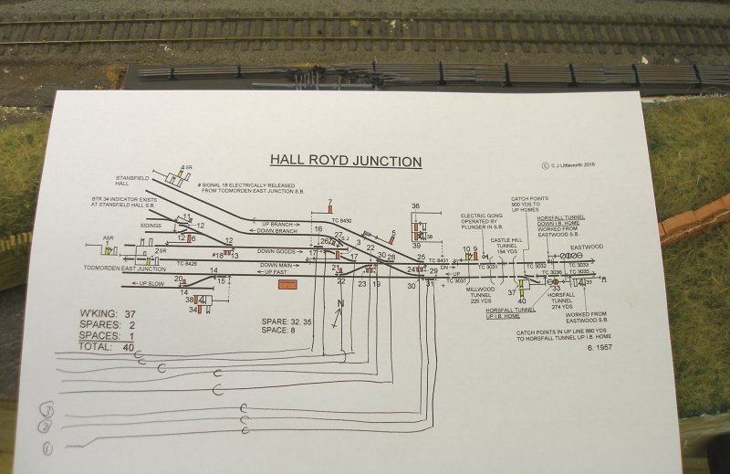
Another issue is linking up the individual pieces of rodding, as the thin rod ends are expected to be but joined to the next section. The first step was to decide how the runs would be laid out, and a copy of the signal box diagram was consulted. This was kindly provided by Chris Littleworth. There are eight rods (as determined from photos) that run eastwards from the box, and the diagram was used to determine what the layout would be.
Observant viewers will spot the error, as lever 30 works both the king point on the Up main and the top set of blades of the single slip. Worse, I've missed off '27' - the worked trap on the Down Copy Pit line. Fortunately no rods that needed adjustment had been laid at the time the error was spotted.
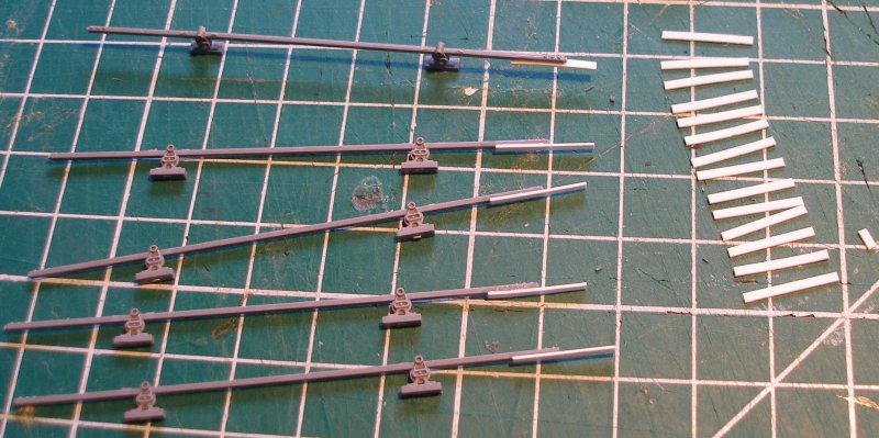
Wills in pack SS0089 provide a comprehensive set of cranks and rods that allow the exit from the signal box to be accurately modelled. The rods were mounted on a plasticard sub-base, and then sprayed with grey car primer. The subtle weathering effects were achieved with weathering powders.
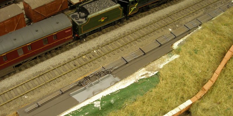
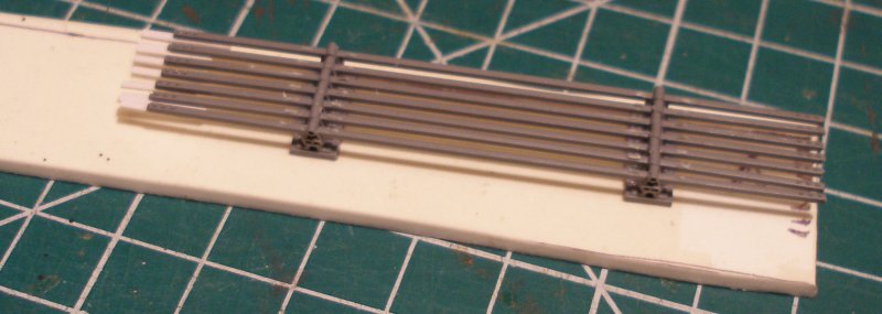
In the image below the rods are being laid towards the pints furthest from the box, and laying has stopped at the place where compensators need to located. The L&YR created a vertical arrangement for such a location, and these are now need to be fashioned and inserted.
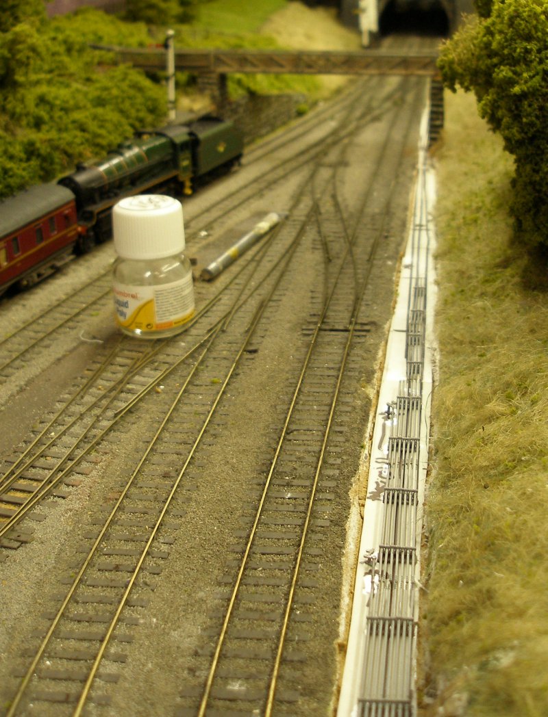
The first attempt to lay straight rodding - as seen in the above image - failed for two reasons. Firstly it was difficult to accurately judge where the rods would pass under the sleepers, and so the decision was taken to build up the rodding runs by leaning over the foreground scenery. But worse, the design requires the rod ends to be butt jointed and the rods themselves became distorted for reasons that are unclear, so it was almost impossible to align and join two rods accurately.
Although there was an investment in the rods already laid, they just looked wrong. So a new approach was required. A new set of rodding was acquired and cut out. To ensure each rod was correctly aligned and firmly fixed to the next rod in the run, a small oblong piece of plasticard was cut for each rod end, as shown below.
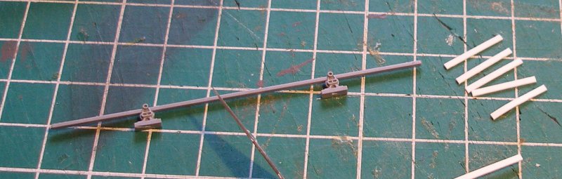
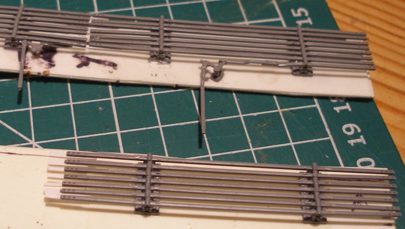
The image below shows a set of rodding now with the plasticard alignment pieces added to the underside of the rod.
The rodding is again mounted on a plasticard base.
Finally, a shot to show how the greatly improved alignment compares to the first effort. The poor alignment between the two sets of rods is very apparent.
9 October 2016
Copyright J K Wallace, t/a 'Hall Royd Junction' 2013-2023 email: Hall Royd Junction
7 Portobello Close, Chesham, Bucks. HP5 2PL, UK
tel: +44 (0)7513 412880