

Making solenoid point motors and
copper-clad points work together in 4mm scale
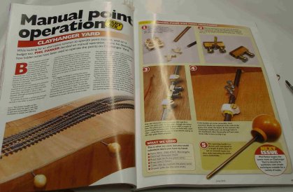
Cover of June 2013 Hornby Magazine which contained an article on point control using piano wire....
How do you make your points work remotely? Does DCC make it easier or more difficult?
My previous layout used copper-clad points worked by Peco point motors, with not much success. Not Peco's fault, as this was a more a mis-match of technologies. The copper-clad points featured sprung blades whereas the Peco off-the-shelf point has hinged blades and are self-latching. In the current generation of Peco bases the self-locking spring has been removed (in essence this was duplicated both on the base the Peco point, so if using Peco points, the spring cover and spring were removed from the base before fitting).
For Hall Royd I decided that one of the problems was that the Peco motor needed a greater throw, and that rather than use the self-latching facility, I would introduce some friction in the assembly to hold the points against the appropriate stock-rail.
I devised a mechanism for under-board mounting which saw the Peco motor on its base plate driving a lever that culminated in a pin inserted into the tie-bar from underneath. This increased the swing, but there wasn't sufficient friction to reliably hold the blades in place.
And if using DCC to operate the points there is the irritating problem that when a train is driven onto a point set against it, the resulting short circuit closes down the entire system. This is extremely inconvenient when four of your points are tucked away in a tunnel (and are the ones you can't see how they are set, and so are the ones most commonly driven through!).
For those who have had problems using the Peco point motors for DCC (the ones with the green motor wrapping), and wondered why there appears to insufficient power, the answer is that they are rated at 1.5 amps, whereas most DCC gear is rated for a maximum of 1 amp. Once I had decided that the points would be switched conventionally, then this was not an issue.
There is also the small matter of cost. With DCC accessory decoders at £30 a pop and 22 points to work (ignoring the signals for a moment), that worked out at £120 just for the decoders.
So the Mark 1 installation featured a signal box diagram using a Peco probe and studs mounted on the panel. I found it quite time consuming to have to look down at the panel to figure out which route I wanted. And - contrary to the 'you only need two wires' school of thinking - I now had a forest of wire under the baseboards.
This all came to sad end when one of the point motors detached itself from the mounting plate, and I realised that the system simply wasn't robust enough either in its ability to reliably switch the points or in its general robustness.
This in part explains the gap in this Web narrative as I pondered this problem for about five months from May through to September 2013. I sell business-to-business newsletters for a living, and one of the old marketing lines was: "Just one piece of information will pay for your subscription many times over...".
Thank you 'Hornby magazine'! The June 2013 contained a two-page article entitled 'Manual point operation' by Phil Parker that described a simple under-board point control system using piano wire (3.18mm). This was - ironically - coupled to Peco 7mm points, but it did seem like a very simple, sturdy, virtually wireless and cheap way of controlling pointwork.
The immediate problem was that the original Peco-based system had been fabricated at the time of track laying, when access to the underside of the baseboards was easy: up in the loft with the boards on their legs and bolted together, turning them over to get to the undersides was not going to be easy. The solution was to construct a sub-frame and remove the legs. There was then a period of about three weeks whilst the sub-frame was built under the existing boards using good old 2" x 1".
The layout breaks conveniently into three sections: fiddle yard and approaches; Hall Royd Junction; and Stansfield Hall Junction and the Engineering Sidings.
The fiddle yard and Hall Royd Junction boards are easy to reach from the control panel, and I have adopted Phil Parker's system virtually as described in Hornby Magazine.
The addition is each rod also works a Peco switch for the frog polarity. To aid fitting, I have glued the Peco switch to a piece of Mecanno, which then provides a couple of handy screw holes at each end to allow fitting to the underside of the board.
The rod working the points giving access to the Engineering Sidings not only works the point tie-bar manually but also switches two Tortoise motors: one for the home signal on the down loop and one for the trap points, and then for good measure also works the shunting signal!
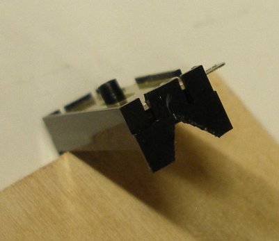
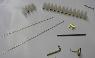
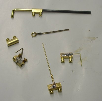
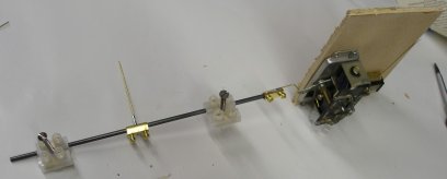
The problem for the points at Stansfield Hall and the Engineering Sidings is that access requires ducking under the return loop, so getting to the handles at the edge of the baseboards for point changing would be awkward. I therefore decided to make the piano wire rods in this section motor worked. As the photos show, it is possible to tailor a wide range of hooks and eyelets that fit neatly into the terminal block innards, and our local ironmongers have a wide range of eyelets and cup hooks that are suitable.
In my stores box I had examples of Tortoise, Peco and Fulgrex motors.
The relatively short throw of the Peco motor was a factor. The Tortoise needed a stronger operating wire, so was put to one side (and I only had two in stock!).
The Fulgrex would probably have worked, but the motor on my recycled example kept falling out of its clip-fit mounting bracket, leaving the motor spinning and the operating rod unmoving.
This left me temporarily stumped, until I remembered having a stock of the old H&M motors in a draw somewhere. A spot of concentrated searching one Sunday afternoon and I was surprised to find I had 11 of them - enough for the task in hand.
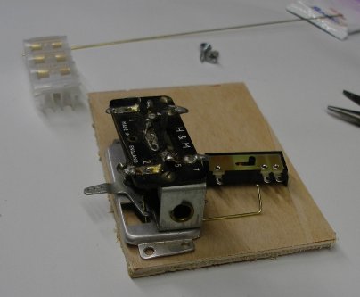
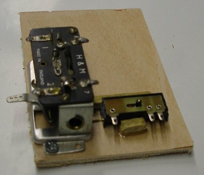
Placing one on the test rig showed it had both sufficient throw and grunt. The weakness of these motors is that the switch contacts are virtually useless, and so a sub-assembly has been created to which the motor is affixed, together with a Peco switch. The switch is driven from the 'spare' leg of the crank, with metal nipped out of the motor frame where the operating wire has to pass under it.
The Peco switch is glued to the ply mounting plate using sections of rocket stick acting as fillets (this is being typed just after bonfire night).
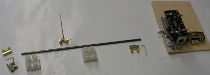
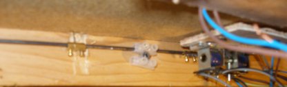
The actual operating mechanism follows Phil's ideas, only I have used pairs of terminal blocks to form the bearings, which in turn are screwed to the underside of the baseboard. I have deliberately made the tie-bar operating rod long so it can be easily threaded through the hole in the tie-bar from the underside. Once the rod is through the tie-bar, it is bent over to stop the assembly falling back through the hole when you are trying to screw the rest of it in place underneath!
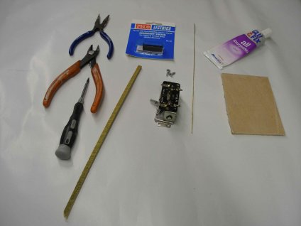
The photos show the assembly process. It should be noted that the wires to the motor and switch should be soldered in place before fitting. This time round I have gone for 'push-to-make' switches which cost more than the probe system but I find them easier to operate.
Posted 13 November 2013
Follow the link for details of the new storage yard March 2014.
Update
But did they work as expected? Yes they did, but as I gained more experience of DCC and started to 'work' the layout, it became apparent that trains, points and signals needed to be worked more consistently.
The trains are worked solely by DCC throttles but the points and signals were worked by a very mixed bag of control mechanisms, with the points being worked by a combination of manual pull rods worked by handles along the baseboard fascia; push buttons on two control panels, plus the two Tortoise motors by one/off switches; and in the storage sidings, DPDT switches set into the baseboard top.
Out of this lot, the push/pull rods (as per the original Hornby Magazine article) have worked very well indeed. The only 'issue' with them was using the Peco PL-13 accessory switch, which have suffered from build quality issues. The final solution was to remove the original PL-13s and replace them with Tam Valley Depot 'Hex Juicers'. The only other issue was the need to increase the degree of friction required to hold the point blades in position, and this was achieved by adding an extra electrical connector block with the screws adjusted to give the required degree of friction. With the Hex Juicer, even quicker now to fit and operate.
So the electrically controlled points have been upgraded on the scenic parts of the layout to rod control.
Although the DPDT switches have worked well, reaching across the sidings to change the points isn't so convenient, and again the plan is to upgrade these to rod control with Hex Juciers.
The downside of the Hex Juicer is cost, which in November 2016, was about £60 a unit or £10 a point.
The upside is ease of installation and reliability. Also, as the Hex Juicer applies the appropriate current as the first wheel makes contact with the frog, there is a chance of the operator having enough time to change the point in front of the approaching train BEFORE the inevitable short circuit occurs. With any form of mechanical switching, the polarity of the frog will always reflect the lie of the points.
The final part of the plan is to work the signals via conventional DCC, as they generally draw less current than the dreaded point motor solenoid.
7 November 2016
Copyright J K Wallace, t/a 'Hall Royd Junction' 2013-2023 email: Hall Royd Junction
7 Portobello Close, Chesham, Bucks. HP5 2PL, UK
tel: +44 (0)7513 412880