
Staging Yard aka Manchester Victoria
It had become apparent that staging was required so that there was somewhere for trains heading to Manchester Victoria to be both received from and despatched to.
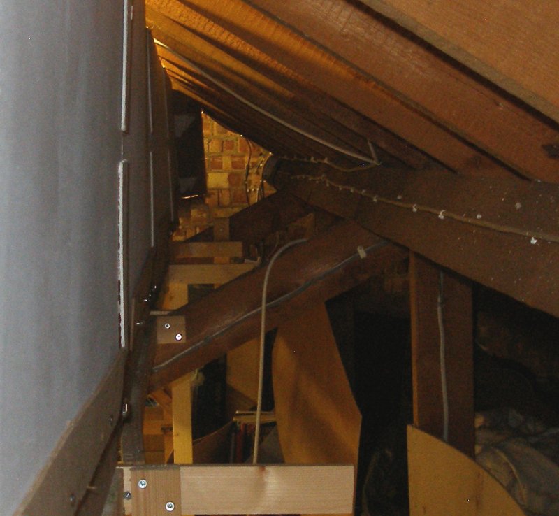
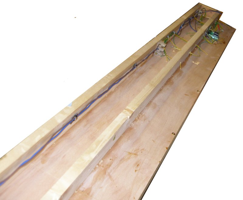
Consequently, staging has been created to fit behind the existing baseboards and backscene. The image below shows the wasted space behind the backscene just calling out for some staging!
Basic construction consists of 9mm DIY-shed plywood, which is handily supplied in sheets of 4' by 2'. This was cut into strips of 4' by 9", and then a framework of 2" x 1" whitewood (pine) created by gluing and screwing the timbers to the underside of the plywood. Because the boards have to fit over the inclined bracing forming the roof timbers, the framework is narrower than the baseboard, so a third piece of 2" x 1" was mounted on the top, outer edge of the board. Again, this was screwed and glued. The glue is Evostick Green Wood glue. I have used other, supposedly stronger wood glues, but found the Evostick product more than adequate for model railway purposes.
As the staging is behind the layout, they are each 8' long, so making their erection easier. They are supported by horizontal pieces of 2" x 1" screwed directly to the transoms.
As this is a DCC layout the 'green' PECO point motors withtheur 1.5 Amp rating, were used. These are mounted above the baseboard using the PECO mounting plate with the centre spring removed (the pints have them fitted). Colbalt accessory decoders were mounted below the baseboard, as once in situ, it will be difficult to reach the programming switch if mounted above the board.
The droppers were soldered to each individual piece of rail and then fed through holes frilled in the baseboard. Gaugemaster layout wire was used. The DCC bus is mains wiring stripped out of its sheathing, and connected to the droppers using terminal blocks screwed to the framing. The connections at the end of each baseboard were also made from terminal blocks, with a piece of excess rail forming the prong of a homemade plug.
Plain track is PECO US-style Code 83 track acquired when a local model shop closed down for half price, connected directly to PECO European-style HO Code 75 points. The Code 83 is fractionally higher than the 75, but they are connected together without any attempt to adjust the heights. In OO the difference is negligible, and the slight 'bump' as trains cross the gap, but this is a lesser bump than observed when OO trains cross a point frog. Being out-of-sight, this won't casue the viewers any grief.
The following images tell the story.
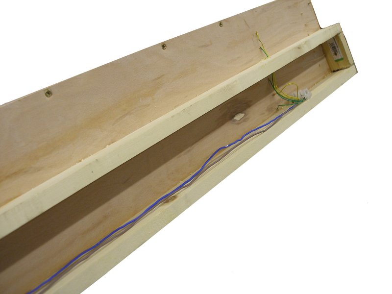
The underside looks like this:
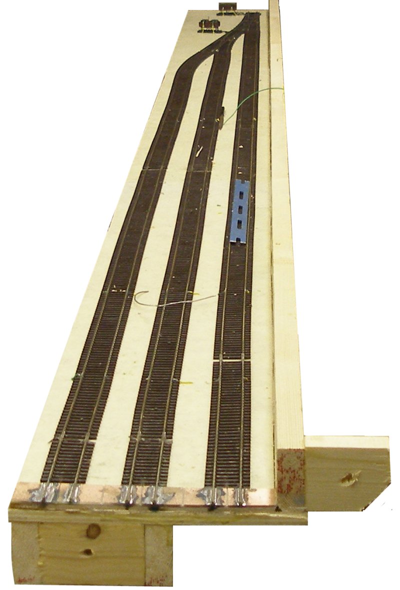
The top of the staging. Note how a piece of 2" x 1" has been affixed to the top of the board. This serves two purposes, as it provides a safety rail in the event of a derailment, and also provides rigidity along the outer edge, as its not possible to fit it below the baseboard top due to the presence of the transoms.
This view shows the underside of the staging, with the bus and droppers now secured using self-adhesive clips. These have proved very effective and easy to install.
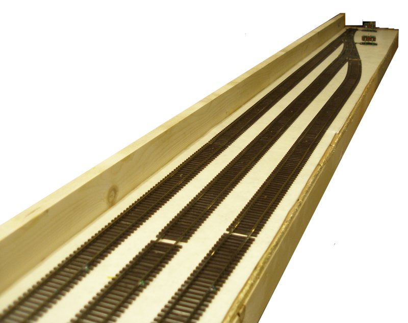
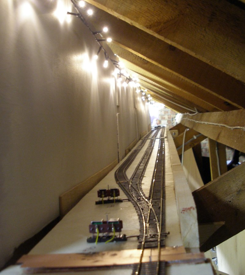
This shows the two staging baseboards now in place, although the track entering the staging in the foreground has yet to be soldered into position and the rails cut.
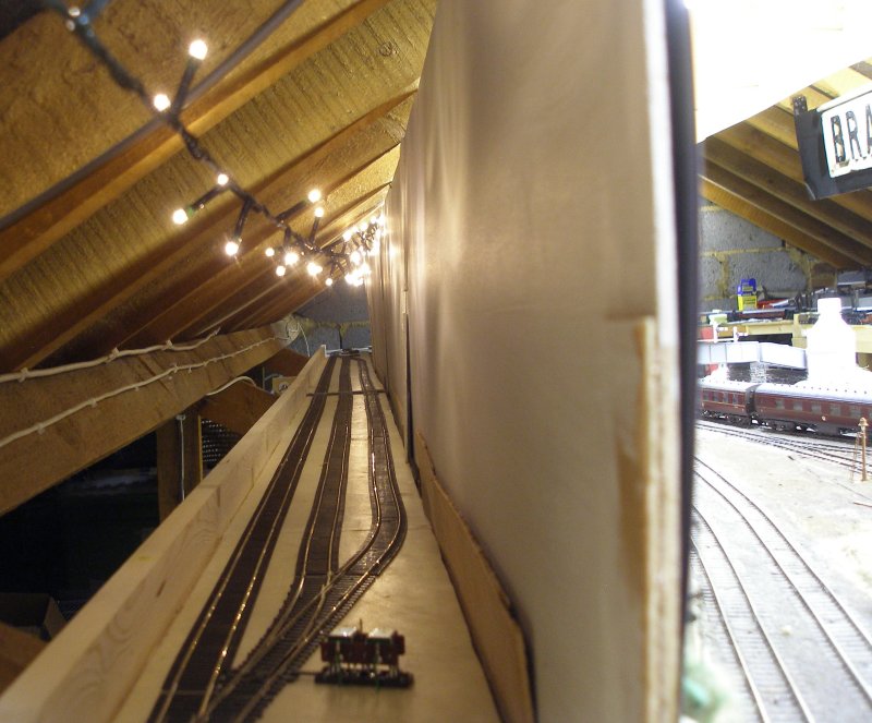
And from the other end. This view shows how the staging sits on top of the transoms and behind the backscene. The flash was switched off for this view, and shows the very effective illumination provided by the string of Christmas tree lights.
To get to this stage has taken a month, although the connections at either end have still be created, and the reversing loop modules on the main layout repositioned, as the staging trackage would otherwise have required additional reversing loop modules.
1 February 2017
In the course of researching possible pointwork the PECO US-style HO Code 83 range was checked over. The range has a superior curved point, with a 36" outer radius and a 32" inner radius - some 2" greater than the OO/HO version. This was spot on for access to the staging from behind the backscene. However, unlike the OO/HO range which has a spigot on the end of the tie-bar, the US range has a hole. This makes fitting the classic PECO point motor fittings difficult.
An e-mail to the PECO Technical Bureau brought the response that a 12 BA bolt should be fed through the hole to create a spigot as shown in the image below. The bolt is in the process of being tightened up.
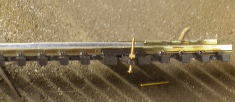
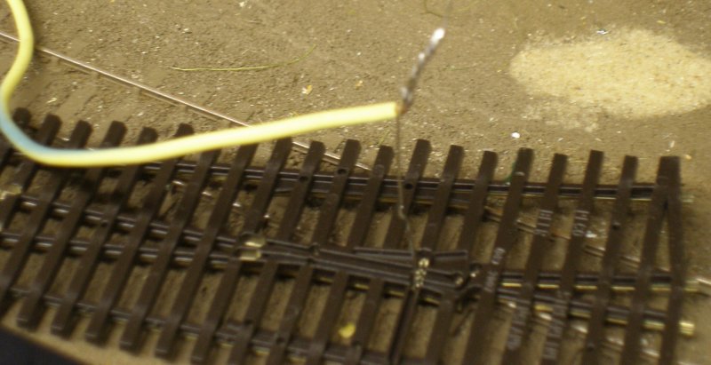
The PECO points have a wire pre-soldered to the frog. This is unwrapped, and the feed wire first twisted to it, and then soldered, as per the p=image below.
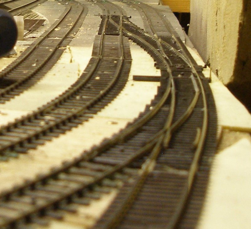
Holes were drilled in the board to accommodate the frog feed and the points laid in place. The middle track still needs to be correctly aligned but the 'perfect' fit on the PECO Code 83 curved point is apparent.
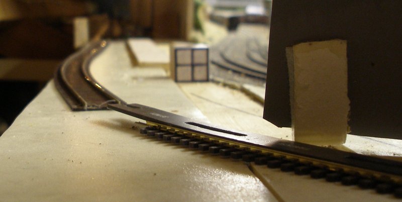
Finally, the connecting track is seen in the image below edging towards the newly installed staging. To maintain a minimum radius of 36" a small extension to the baseboard will be required to the left. The plan is to lay the track and then accurately cut the baseboard extension to support the track where it overhangs the baseboard edge.
7 February 2017
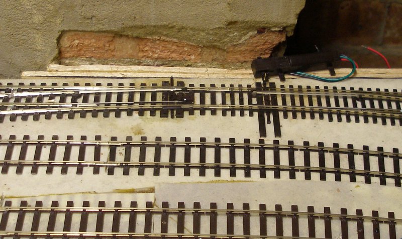
The track forming the exit from the staging is now complete, and now attention is turning to sorting out the electrics. The great beauty of fitting in new trackage retrospectively is that points and motors have to be fitted where points and motors were never intended to go. So it proved with the baseboard framing and chimney breast. I didn't see the point of cutting into perfectly good baseboard framing, as the following image illustrates.
Often on the Facebook model railway groups the subject of whether DCC is worthwhile or not is raised. These points giving access to the staging are an excellent example of the benefits of DCC.
The two 'King' points for the staging are located at opposite ends of the layout, some 24 feet apart. The beauty of using the Cobalt accessory decoders is that the decoder is close to the point being worked, and is powered directly off the traction bus. The two points are programmed with the same accessory number - in this case '93'. So when '93' is selected on any of the throttles handily spotted along the layout fascia, both points are fire together.
The bad news is the cost of the Cobalt decoders. The good news is short wiring runs, and handy operation from anywhere in the layout room. This pairing of turnouts also applies to the staging itself, with the points giving access to the loops ('94') and loop points ('95') also being fired simultaneously. So far the Cobalt claim of 'fires ever time' has proved to be the case. Having given some thought to train detection for the staging, I finally opted for a mirror (£3.99 from the local Pound Shop) and a string of redundant LED Christmas tree lights. With the mirror carefully angled, it is possible to see one set of the points '94' and '95' from the normal operating position, and see they how they are lying, along with the current occupation of the loops.
10 February 2017
Copyright J K Wallace, t/a 'Hall Royd Junction' 2013-2023 email: Hall Royd Junction
7 Portobello Close, Chesham, Bucks. HP5 2PL, UK
tel: +44 (0)7513 412880