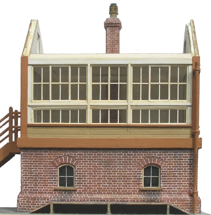
Building a Lancashire & Yorkshire Signal Box in 4mm scale
"Assumption makes an ass of you and me" as my old Army chum Nick use to say.
Back in 2012 when I was planning my model of Hall Royd Junction there were very few buildings required, and beside the two signal boxes, the only other structures were two hen houses and a Permanent way hut. Consequently the Hall Royd Junction signal box was going to be the signature structure, and therefore should be modelled to a 'good' standard.
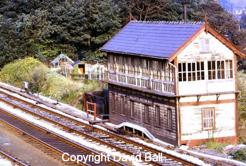
To do this I would need a plan and photographs. The photographs were easy as the Lancashire & Yorkshire Railway Society has some excellent shots of the front and back taken just before the box was demolished (LYRS 6021, 10657 and 10658), and David Ball of Sowerby Bridge also had a couple excellent colour images taken in 1972. These very clearly show the highly distressed paintwork just before demolition. The LYRS have also acquired a series of slides from the Todmorden Antiquarian Society taken at the time of demolition. These are particularly useful for showing how the box was constructed.
So that left finding a plan (drawing). My first port of call was a plan drawn by LMS Society member Arthur Whitehead of Dewsbury East in a 1964 issue of the 'Railway Modeller'. And this is where Assumption cost my a few years in model building!
Arthur's plan look somewhat disproportionate to me, squatter and wider than I thought a LYR 'standard' box should be. This view was supported by other plans and photographs I found, notably in 'Modellers' Back Track' Volume 4 Number 6 dated February/March 1995 (incidentally the last of the series). This contained full page (A4 landscape) diagrams of a wooden box (3-4-3) front and door-end elevations, and a plan of the front of a brick box (4-3-4). There was also a series of thumbprint plans showing various window configurations and heights. It was these plans that were to mislead me, as I assumed that 'standard' meant, err, 'standard'. As chance would have it, Arthur had measured Dewsbury East literally days before it was demolished, and his plan had been drawn from the sketches and measurements taken on the day of his visit.
Looking at my Hall Royd photos, the non-door gable end had two sets of three sliding windows, and using the dimensions provided in 'Back Track' it seemed that the plans were wrong, as they showed a narrower end configuration. The next port of call was Tom Wray's 'Lancashire and Yorkshire Railway Signalling' published by the LYRS. This has a great deal of signalling detail, but the signal box plans looked very like the ones that had appeared in 'Back Track'.
The same diagrams, although better printed, appear in 'The Signal Box; A Pictorial History and Guide to Designs' by the Signalling Study Group (pp. 102 - 103). None of these plans seemed to depict a box like the one at Hall Royd. And they did not scanned particularly well, so capturing them for manipulation on the computer was a challenge. This was exacerbated when the diagrams were printed to a small scale, such as Arthur's Railway Modeller plan, which was to 2mm scale.
The best plan for my purposes (large all timber box) was found in 'A Pictorial Record of L.M.S. Architecture' by V R Anderson and G K Fox (OPC 1981) figure 69. Although very small scale, the printing is of a high quality, allowing the plan to be scanned and easily blown-up. Incidentally this seems to be an LMS plan, and differs from the others I had found which seemed to be from the same source. This allowed the Mark 1 diagram to be drawn-up and printed to 4mm scale to allow the assembly of a card mock-up to be placed on the layout to fill the otherwise bare baseboard. This is not an original idea but was originally explored in the LYRS Magazine by Ken Carter.
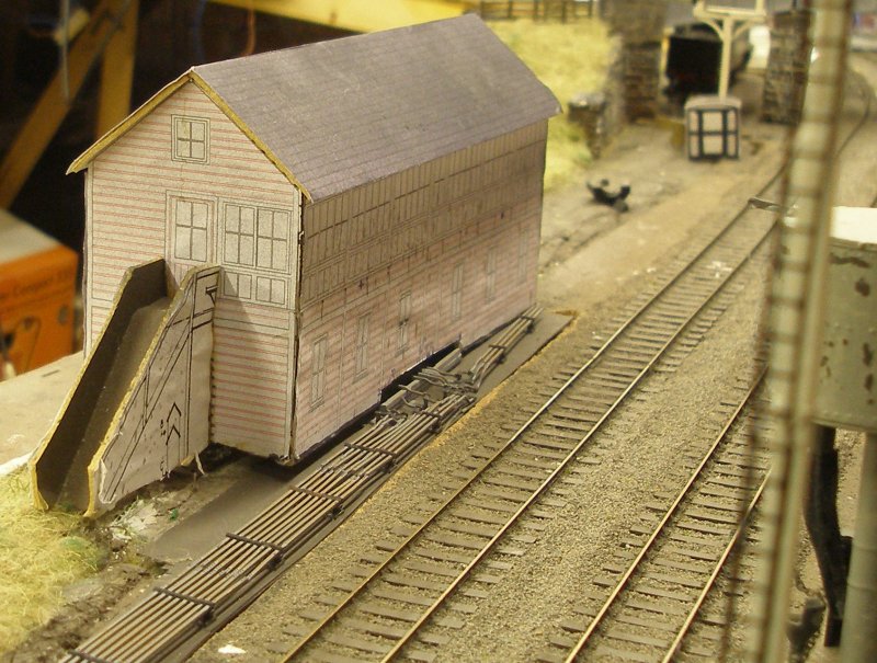
I still wasn't happy with box plan, feeling that I still hadn't 'nailed' the look of the original. Nonetheless, I decided to print out the plans and assemble a card quickie to judge the appearance and location of the final model, as suggested by Ken Carter in a LYRS Magazine some years ago. Here is the outcome:
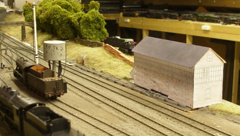
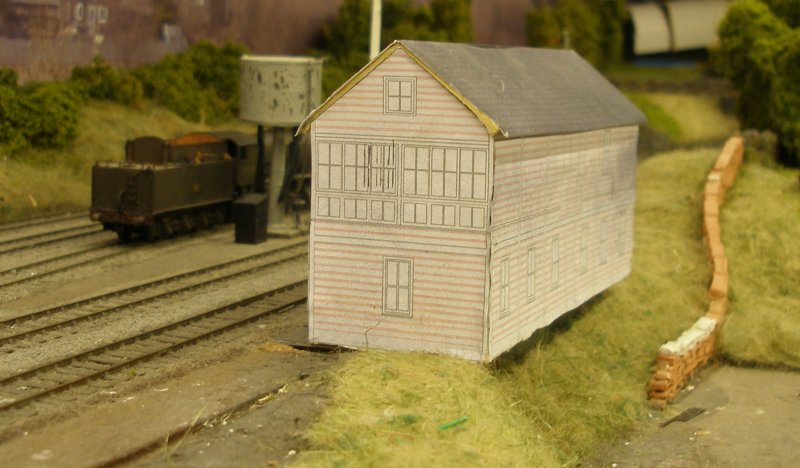
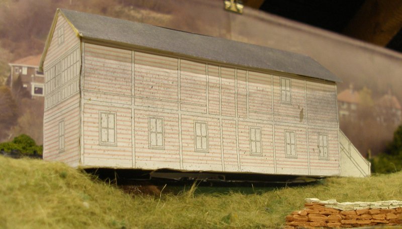
An article in the 'Model Railway Journal' describing the construction of a Midland Railway signal box close to Bristol Barrow Road MPD using the laser cutting technology of York Models greatly appealed. This would require transferring the plan to an alternative computer plotting programme, as none of my art-based programmes were recognized by York. It is also a relatively expensive process, so one has to be very certain of the final art before committing. In the meantime, 3D printing was also coming forward in leaps and bounds. It was apparent that whichever of these two routes was selected would require me to buy and master new computer programmes, and I know that this works best for me if I can be mentored, so this didn't seem to be a viable option. I was also fighting shy of building a model conventionally as Hall Royd was a relatively large box. At about this time I produced a down-loadable LYR Type 6 card model, and offered it through this Website.
This all delayed production of the model, but as there were other layout building priorities, and that's how things stayed for the next 3 years.
Then Martin Nield was guest editor of the December 2017 issue of 'Model Railway Journal' and included an article by Gavin Clark on the construction of a LYR brick based signal cabin. Gavin provided a detailed description, and this was the prod I needed to pick-up the scalpel.
In Gavin's article he referred a some LYR signal box windows frets produced by a 'LYRS member'. I knew of these, as I had purchased a pair back in 2013...but could I find them? Neither could I find details of the supplier. I am therefore very grateful to Barry Steventon via the LYR Yahoo! group, who pointed me towards John Taylor of Uncommon Kits. John can be contacted at Moorend Cottages, Steep Lane, Sowerby Bridge, West Yorkshire, HX6 1PE (e-mail: jar56 at btintermet.com).
These are based on Hebden Bridge, which is a brick-based box, so an alternative source of locking room windows would be required. This highlighted the need for a drawing of the box. The first 'dividend' was the discovery that the locking room window frames are identical to the sliding panels above.
A small detail which is apparent on Hall Royd is the orientation of the steps. These face towards oncoming traffic passing the box on the adjacent track, and is a feature of the vast majority of signal boxes in the UK. This was to allow the signalman the opportunity to see an approaching train before stepping off the bottom of the steps. Blackrod, which controlled access to the Horwich branch, is one exception.
Gavin made reference to H. Raynar-Wilson's two-volume treatise on "Mechancial Railway Signalling", as reprinted by Peter Kay of Orchard House, Teignmouth, TQ14 8DP. The first volume has the larger scale plans and diagrams for LYR boxes, including some smaller one showing various configurations of wooden boxes. The various diagrams of LYR relevance are:
Fig. 51 Wood & Brick Signal Cabin: Lancashire & Yorkshire Railway (front elevation and internal framing + floor plan) (large scale)
Fig. 52: Wood & Brick Signal Cabin: Lancashire & Yorkshire Railway (cross-sections featuring window arrangements at both ends) (mid scale)
Fig. 53: Wood & Brick Signal Cabin: Lancashire & Yorkshire Railway (door-end showing external lavatory and balcony detail) (mid scale)
Fig. 61 Wood Signal Cabin: Lancashire & Yorkshire Railway (front and two end elevations) (small scale)
Fig. 66 Overhead Signal Cabin: Lancashire & Yorkshire Railway (front and one end elevation) (small scale) (St Lukes, Southport electro-pneumatic)
Fig. 67 Overhead Signal Cabin: Lancashire & Yorkshire Railway (front, one end elevation & floor plan) (small scale) (Liverpool Exchange No. 1)
Fig. 68 Cast iron Window Frame (front and cross-section)
Fig. 70 Cast Iron Wall Box (as per Figs 51 & 52)
Fig. 71 Coal and Ashes Place
Fig. 72 Nameboard for Signal Cabin
Fig. 73 Arrangement of Sashes in the side of a Lancashire & Yorkshire Railway No. 9 Signal Cabin
Fig. 76 Landing for Window Cleaning
Fig. 82 Steps for Signal Cabin: Lancashire & Yorkshire Railway
There are other diagrams which are not line specific, but all show typical arrangements.
For completeness, the chapter on signals has plans for a two-arm tall siding signal; three-doll bracket; finial; standard Raynar Wilson arm; Hart's slot compensators, Dwarf signals, etc.
The LMS erected LNWR-type signal gantries at Hall Royd and Low Moor, and the book also contains a plan of their big cousin at Rugby.
These were used to produce a new plan (my original plan turned out to be correct in all key features but lacked refinement), as seen below. The 4mm scale plan is available as a downloadable PDF.
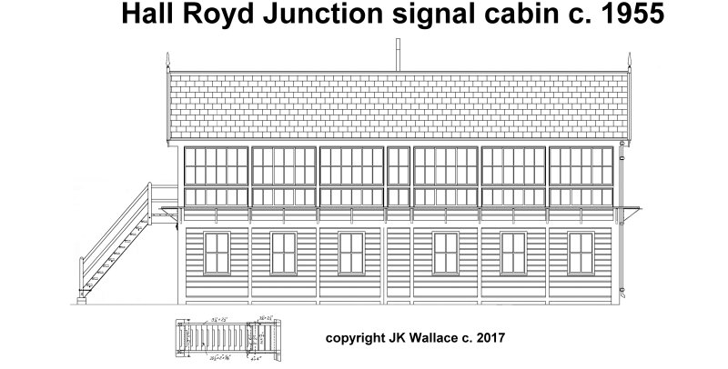
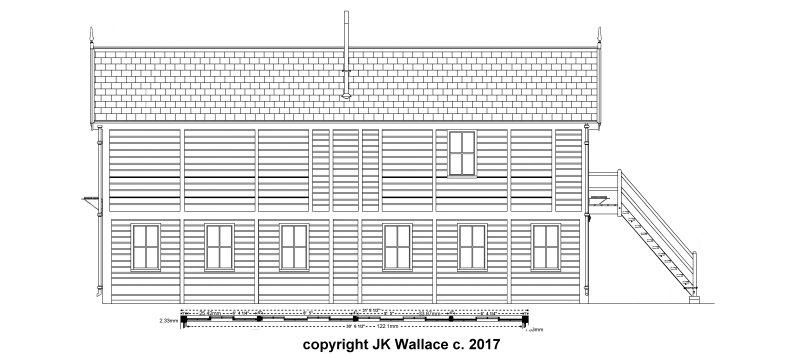
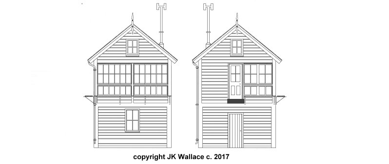
Notes on the drawing.
Hall Royd is a strange box in that it is much longer than the frame it held, with a large vacant area at the Manchester end - it must have been jolly cold up in the Yorkshire Pennines in mid-winter! The rear of the box has a certain home-spun feel to it, particularly the central upper paneling where it is formed into three narrow vertical panels, with rather rough and ready siding, almost the sort of thing you might expect to see on an allotment. The stove is immediately behind this panel, and begs the question whether at some time the fire escaped from the stove, and this is the resulting rough-and-ready repair. There is also a similar panel of non-standard boarding cut into the right hand upper frame, forming the rear outer wall of the internal toilet. It seems unlikely that there was also a fire in the toilet, so these two distinct areas of rough paneling remain a mystery. Needless to say, it was only in the last few years that photos of the rear were taken, and it is not currently possible to say whether the box was built like this (unlikely) or when the repairs were made. In his wonderful treatise on mechanical signalling, Raynar does make the point that the primary elements of a wooden box need to be replaced at approximately 25 year intervals, and on this basis the box might have seen two such upgrades, c. 1929 and 1955. Chances are that the latter one was deferred.
The door-end of the box is more conjectural, simply because I have so far not located any close-up photos of it. The best so far is one taken by Eddie Bobrowski from the footbridge in 1968. This confirms the broad configuration but the locking room door and window-cleaning bracketing is conjectural. The locking room door is based on Arthur Whitehead's Dewsbury East drawing on the basis that they were similar looking boxes on the same side of the Pennines and on the same line!
The 'H' shaped extension piece to the chimney had been 'lost' before the box was demolished. Also not shown in the drawing, it had acquired a series of small windows cut into the two left-hand front lower panels, next to the locking room windows, and a rather crude pipe out of one of the upper panels, close to the internal toilet next to the door.
The box is shown in its full glory with the non-door end window frames still present and not boarded over. Over time the bottom, fixed row of 12 windows were covered up; the right hand set of six went first, followed by the remainder in or around 1965.
This leaves the question of how the siding was continued under the eaves, which, of course, are hidden by the overhanging edge of the roof. Very good advice is not to base a model on a model but there's nothing like being able to peer over someone's shoulder to see what they have done. In this case, Peter Leyland's model of Kirkby is to hand. Not only has Peter made a very neat job of the windows with micro-strip, he has not provided any detail above the sliding window frames.
