
Relaying of a Cross-over on an existing layout
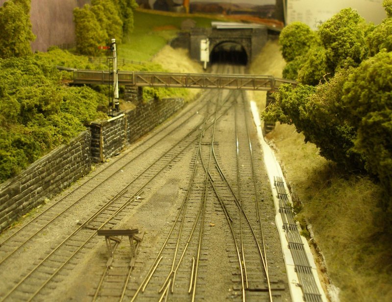
When Hall Royd Junction was originally schemed out it was intended that the layout would be built in 4' x 2' modules, and that the principle 'block' of points would all be contained on one baseboard. As well as the double junction with its single slip, there was a cross-over between the up and down main lines.
Although the layout is based on a prototype, at the time of starting construction, the purpose of the cross-over hadn't been determined, and it was assumed it was for use by light locomotives. It was only after viewing some of Richard Greenwoods's remarkable film archive did its purpose become apparent. Todmorden had a triangle which was used to turn steam-powered rains, and in particular trains from two directions; empty excursion stock from Rochdale which was turned and then formed an excursion to the seaside; and the three-coach locals from Blackburn.
To fit the available space, the cross-over was formed of points with a radius of 30 inches (2 foot six inches). However, when both the excursion rake and the Blackburn 3-coach local set was propelled over the cross-over there was buffer locking and regular derailments.
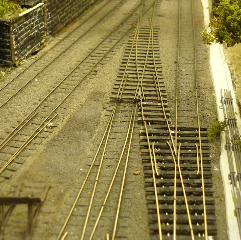
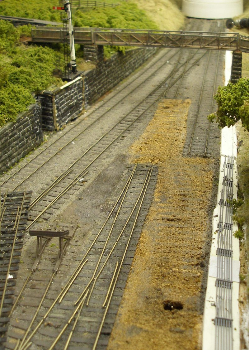
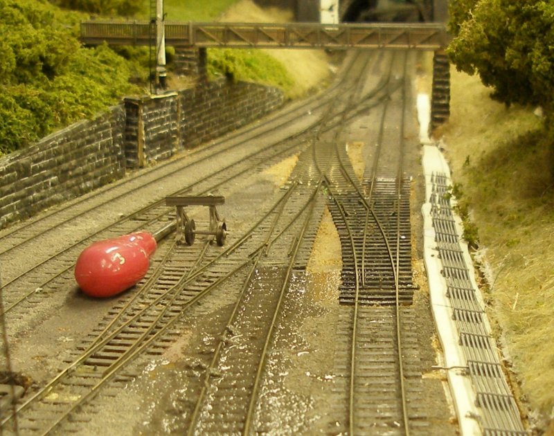
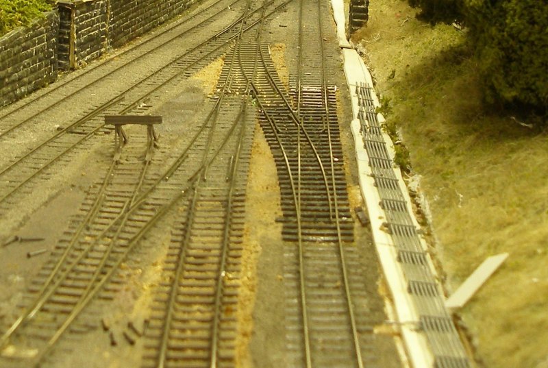
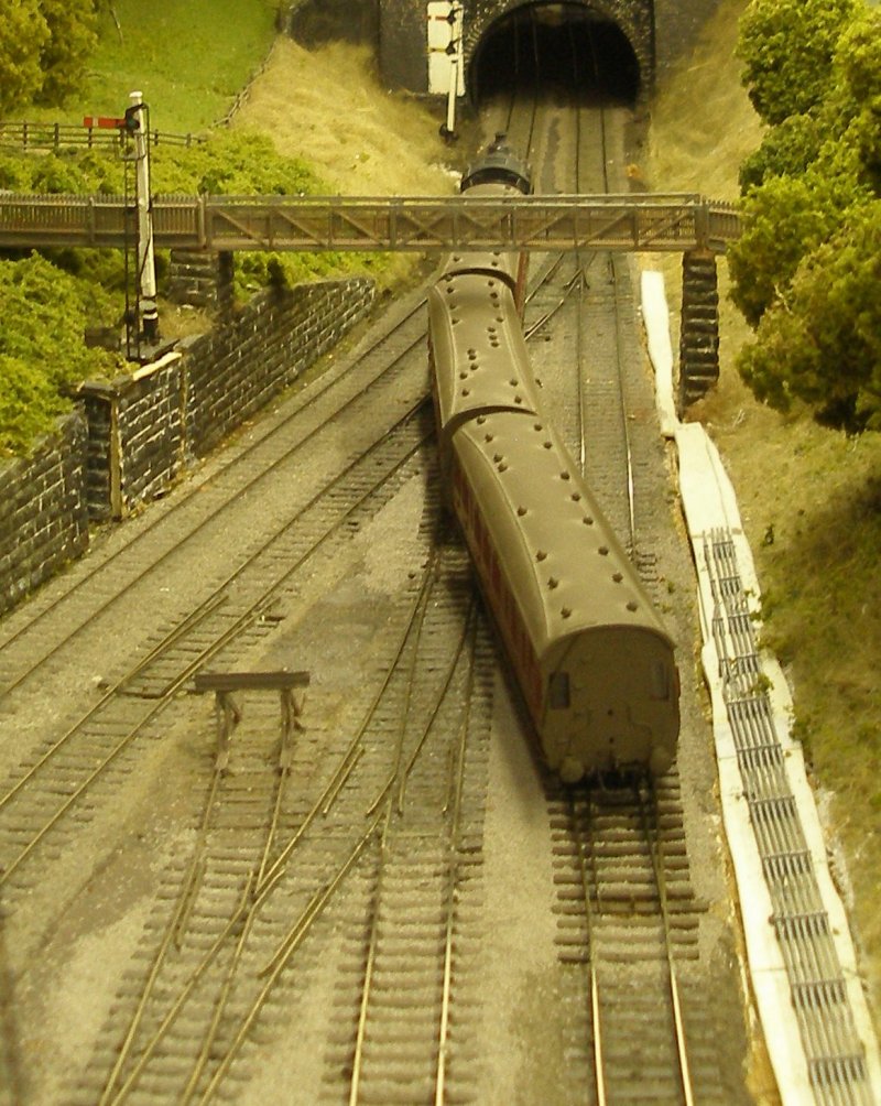
View showing the 30 inch radius points forming the original cross-over .
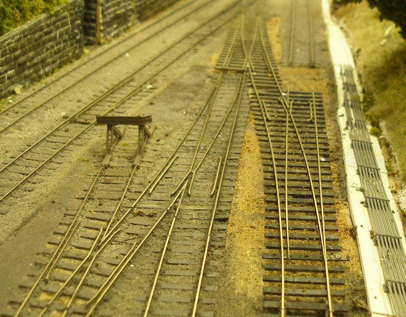
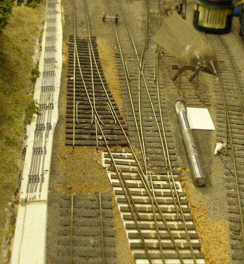
The first move was to lay out the replacement 60 inch points alongside the original point. The visual improvement is immediately apparent, but as can be seen, the switch blades of the new point are going to very close to the check rails of the adjacent point, and careful cutting is going to be required.
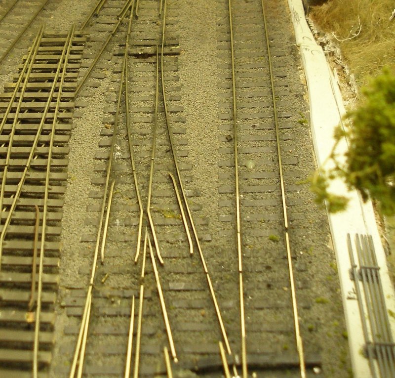
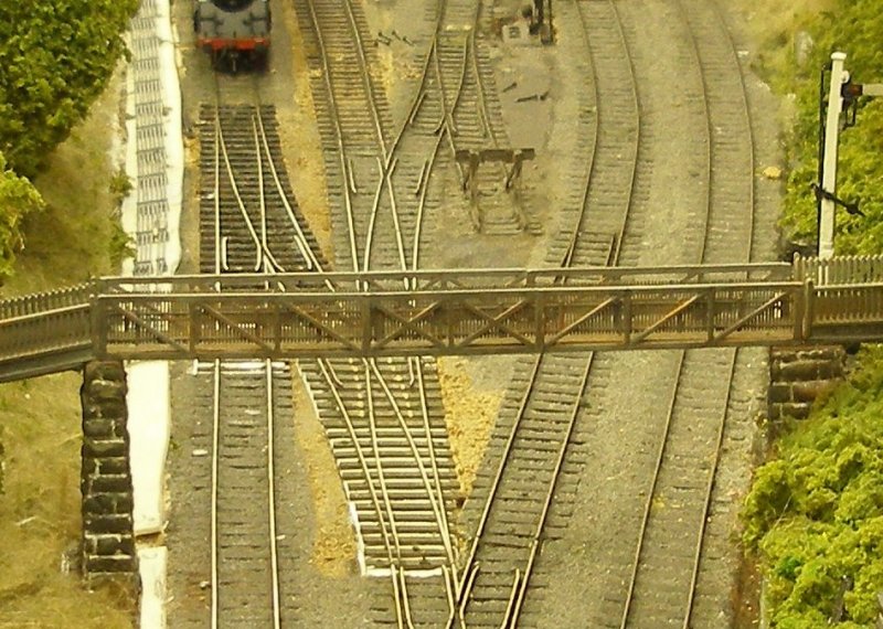
After careful trimming of the new points, the pair forming the cross-over can be laid out. The old and new alignments can be compared.
Now the old points have to be lifted. They were originally laid on cork underlay, and ballasted with Woodland Scenic ballast secured with diluted PVA. Hot water from the kettle was gentle poured onto the track to be lifted, and then - with the track pins removed - the points were gentle teased up using a screwdriver.
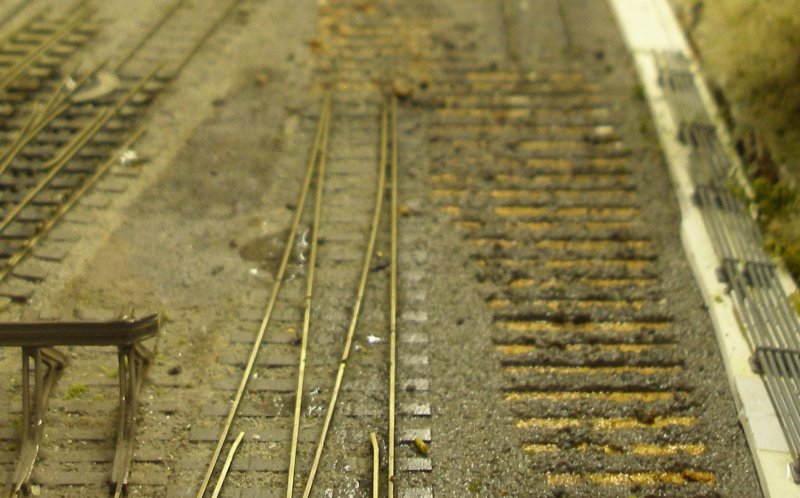
Then the ballast was scraped away using the flat end of a metal ruler. The slot and actuation rod for the old tie-bar can be seen in the roadbed in the foreground. New slots will have to be cut, and the manual operating arms repositioned.
Now the new points are laid in their new positions, and careful cutting of rail ends undertaken to get a final fit.
Then the new dropper wires were soldered to the underside of the rails: green for the frog which will be connected to the Tam Valley Depot Hex Juicer; and blue and brown for connection to the bus wires.
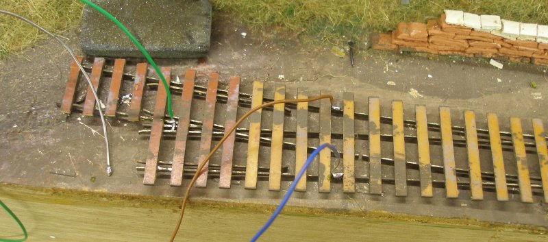
The point is rotated and the wires inserted into the pre-drilled holes.
However, it was apparent that there was a mismatch in rail height, and that the underlay would have to be cut out. The new slot for the tiebar actuation rod can be seen cut through the white square of plasticard, whilst the original is the hole a couple of inches to the left.
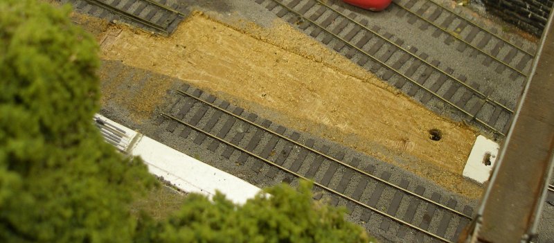
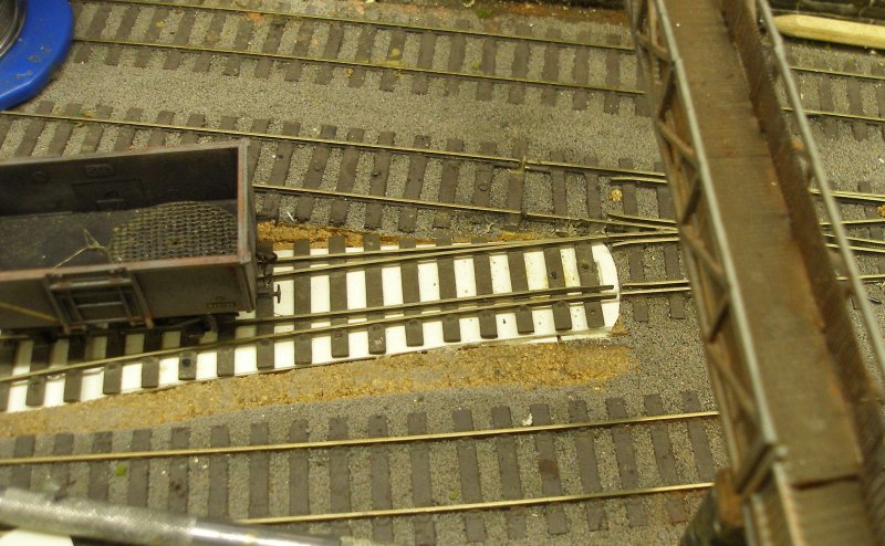
A plasticard packing piece was now fitted into the gap in the underlay to get the correct rail height. This was carefully tested using a wagon.
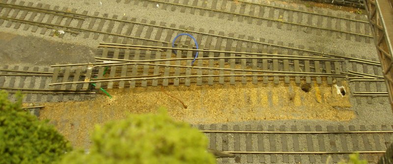
Now the second point has been paid in place, and it can be seen that gentle teasing is required at both ends of the point.
Now viewed from the other end, it can bee seen that the rail joints re now correctly aligned, and now another piece of track is being lifted to correct a historic misalignment. I really must get round to finishing the Will's point rodding.
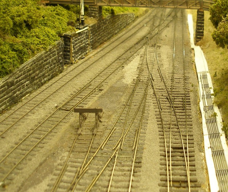
And now the new plain track has also been laid in.
With all the new track laid, aligned and wired, now it is time to try a loco running over the points in all directions.
Ballasting was then completed. The ballast was gently brushed into place and then secured with diluted PVA and a drop of washing-up liquid.
Final testing involved the trains that have to use it. First is the Crab-hauled Rochdale excursion rake, which runs forward through the cross-over to reach Todmorden station to pick-up its passengers. It arrived at this point by backing down the track on the left.
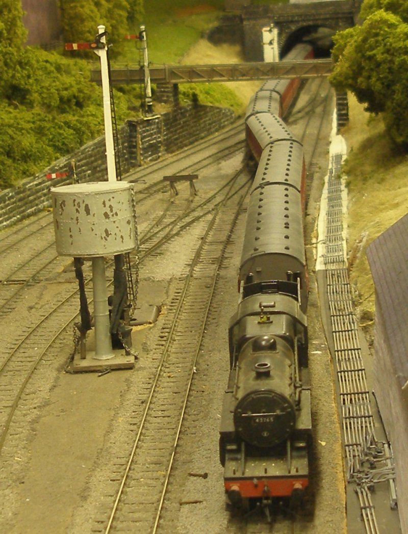
Finally, the Blackburn local takes its turn, and is reversed over the cross-over.
Copyright J K Wallace, t/a 'Hall Royd Junction' 2013-2023 email: Hall Royd Junction
7 Portobello Close, Chesham, Bucks. HP5 2PL, UK
tel: +44 (0)7513 412880