
High-level storage yard and incline (aka Manchester Victoria)
When planning a model railway, do you develop an imaginary backstory or do you select an actual piece of railway? There is no right or wrong to this; both are great fun. I only thought about this the other day as one of the Facebook posts had asked members to post their thoughts on why they had taken the course they had. My final take on a 'real' piece of railway is that you have all the fun of selecting and building the trains, and the scenery, plus you have to research the history of the place. Both how it looked on the period you have set, but along the way, you start to collect timetables so you can get a feel for the type of trains, their frequency and at what times of the day they ran...and most critically, where they ran from and to.
In the beginning, the first idea for Hall Royd was a set of storage sidings at one end of the loft (Leeds) with trains running through the (scenic) junction and then entering return loop so that behind the backscene the coal train bound for Copy Pit became a train from Manchester and passed back through the junction before entering the storage yards again. This didn't really work, so the storage sidings were relaid along the other side of the loft (the area I'd originally planned to put Todmorden station. This then allowed a continuous run to be formed for Copy Pit trains (so the mineral trains could not be sexed as loaded or empty), whereas the Manchester-bound trains had to pass back down the Copy Pit line to regain the storage sidings.
The third development was to create a set of three through storage roads (staging in US terminology) behind the backscene to represent Manchester, so allow Manchester trains to either terminate there, or continue through to the storage yard proper. It was obvious, however, that the storage yard had insufficient capacity, so it was lifted and relaid with the tracks closer together, and more short dead-end roads in the spaces at ether end of the yard for DMU stabling.
This still saw trains to and from Copy Pit/Rose Grove mixed in with trains supposedly arriving and departing from Manchester. But there was nowhere to create additional storage capacity. Just before Christmas 2019 there were a number of Facebook posts asking what the steepest practical gradient might be. I didn't know, but an upper storage areas seemed like a possible solution to the Manchester problem, particularly as there was a 'dead' area in one corner of the loft which couldn't be easily accessed from the lines at baseboard level.
There is one junction that allows trains to access all parts of the layout, and this was the logical starting point for the incline to connect to the upper storage area, and also the obvious starting point for construction.
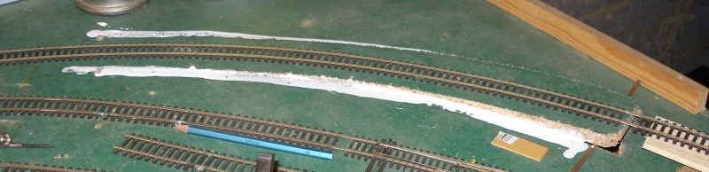
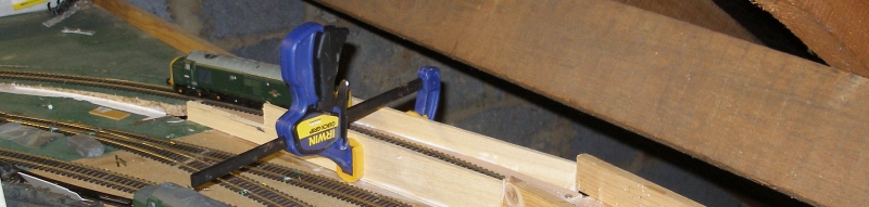
The first step was to create the rising baseboard to form the foot of the ramp. This was achieved by drilling two holes either side of the track through the chip board, and then running the jig saw down each side (and between the two holes) so that a the track bed could be gently raised. It was then secured with two pins driven in side ways to the raised trackbed, and then a fillet of PVA wood glue run down each side as shown in the photo below. The track to the right terminates on a piece of board that at this time launched out into space and was held in place by timber off-cuts and clamps.
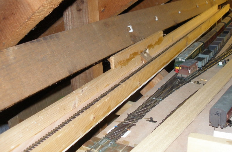
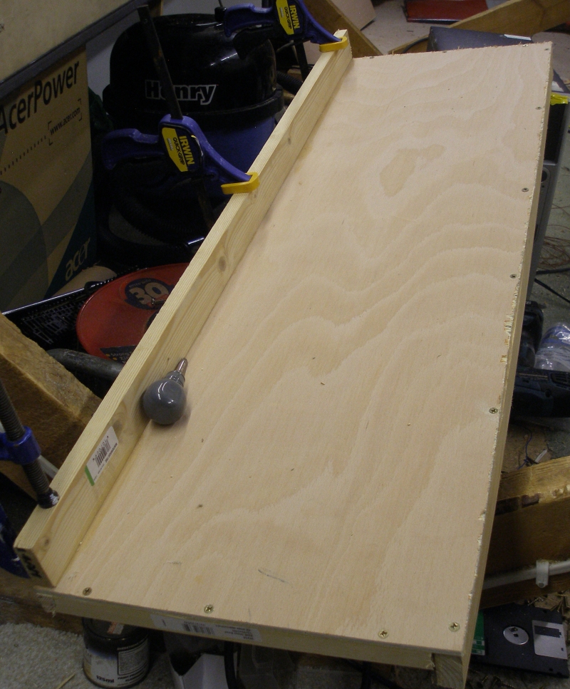
Stage 2 was to create the body of the incline. This was formed from a plywood base with 2" x 1" edging. (above rather than below to stop trains plummeting to the floor). Note how a section of the rear framing has been removed to accommodate a roof truss. An additional piece of 2 x 1 has been glued above the gap, and then, rather conveniently, the who assembly secured temporarily by a wood screw.
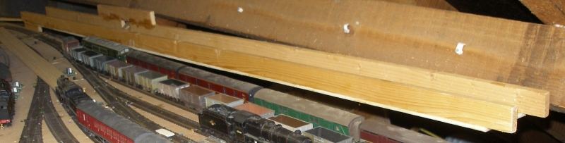
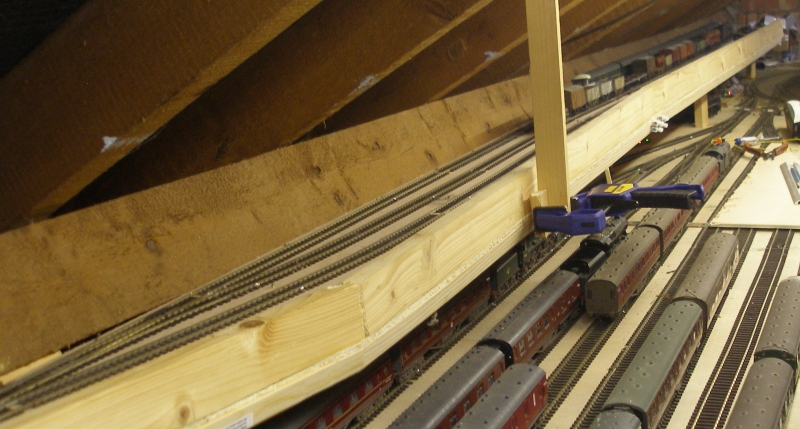
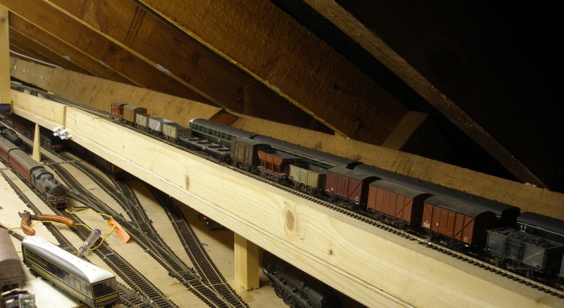
And here it is in its entirety. It can be seen that the end of the incline appears to be above the roof line of the vehicles below
 .
.
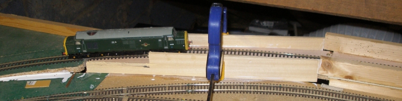
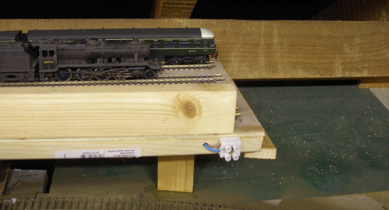
Having successfully established that trains can climb the grade, the bottom end was tidied up, with side panels added, and seen here clamped in place whilst the PVA sets.
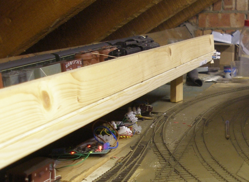
The three boards to form the stage are were constructed to an identical plan, again with 2" x 1" timber above the board on the front edge to maximize clearances below the boards, whilst the rear edge was below the board, and this was in a clear area, with no storage lines directly below. However,to minimize any warping, material from the local Wikes beading section was used to create a frame under the board.
n the view below the first two boards have been erected. They are actually canter levered off the loft timbers using the metal rods sold by stationers for desk-top filing trays. I found four rods in my tool box (long rescued when the office was throwing out the old filing trays) and then it was discovered that the local stationers sell packs of 4 rods for £1. So two holes were drilled into the loft timber at right angles to the timber; two matching holes in the side framing of the board; rods inserted, and the storage yard gently slid into place. To provide support, a truss was 'hung' from the rafters and screwed to the front side framing. With the other two boards, there was room underneath to site legs.
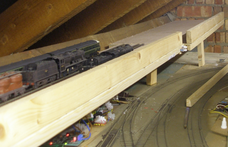
The shot below shows the location of the second board, with the third, shorter board still to be fitted. Note the legs supporting the front of the board.
To try and reduce the incline grade, the first storage board is actually on the grade, and the gradient eases at the joint between the first and second boards, as shown below. The brakevan is on the first board (inclined) whilst the box van is on the join, and the rest of the train is on the level. The yard has four roads, and to give a degree of flexibility, the roads are slit on the second board with a connection formed of two right hand points and two double slips so that when shorter trains present themselves, it will be possible for the rear most trains to exit the yard via the access rack (the rear road on the first baseboard). Note also the terminal blocks to the left of the brake van on the side of the framing for the bus wires to be connected between boards. The piece of plywood just behind the suburban coach on the lower level was there to maintain the correct height whilst the final support were added.
The first two boards were aligned again using the steel rods provided for the filing trays. One was cut in half to make two dowels, and these were glued into their holes on the baseboard edges so that the rear dowel protruded further than the nearer one to aid fitting the board. But board three was more problematical, as it was going to butt against the end wall of the loft, so there would be no wriggle room to allow the doweling to be aligned. So a ledge was created on board two on which board three could sit.
In the shot below board three is now located. It is wider than the previous boards as there are now no issues with access below, and I find any extra width a benefit when trying to re-rail or uncouple stock. Again, the terminal block is in place at the end of board two ready to carry the bus wire forward. The tracks curving in from below are the Manchester lines having exited the scenic section, and trains bound for the new upper level boards will have to complete a full circuit around the loft and behind the back scene before arriving on the upper boards.
To make life easier - and to simplify construction and keep costs low - these boards are all laid with second-hand PECO Code 100, and all points are insulfrogs. I found on the Internet a suggestion that the insulfrogs be laid with insulated rail joiners, so that the blades are only powered-up when the road they relate to is selected. This has worked very well and has meant that the points are DCC friendly without further modifications.
Finally, I will add some notes on how the track crosses the baseboard joints, as the technique differs from that used elsewhere on the layout (an idea first shown to me by Alan Needham in Southport) and also on the canter levering.
I will also take some snaps of how the droppers and bus wires have been fitted.
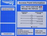
I am also minded to buy some BR diesel-era depot badges as advertised on eBay, as these can used to mark out the tracks by their prototypical location. These include one for 'Manchester Victoria MV' which can't be an original stabling point, as it would surely have been 'Newton Heath NH'? But 'Manchester Vic' would work better in a layout context, and would greatly assist visiting operators.
Copyright J K Wallace, t/a 'Hall Royd Junction' 2013-2023 email: Hall Royd Junction
7 Portobello Close, Chesham, Bucks. HP5 2PL, UK
tel: +44 (0)7513 412880