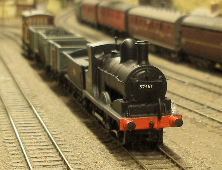
AJModels Aspinall Cass 27 Lockdown project
The Hall Royd layout is set in a 1966 -1968 time frame, by which time the last of the Lanky locos had been banished to the scrapyard. Worse, most of them in their last days were confined to points west of Manchester. A notable exception was the surviving Pug at Bristol.
It seemed wrong to have a Lanky layout without a token Lanky presence, and the last Lanky loco in traffic (excluding the Pug) was the Aspinall 0-6-0 (Hughes Class 27) which was retired from Sowerby Bridge in 1962.
An unmade MPD kit had been sitting on the shelf for at least four years, and each time the box was opened looked 'complicated' so was put back on the shelf.
RMWeb had previously revealed that the Bachmann Class C chassis was a dead ringer for the Class 27, and had been successfully mated with the body of a previously made kit. This in turn had led AJModels to create a 3D printed body and tender kit via Shapeways.
These facts had been filed away, and an on-going search maintained on eBay for a budget pre-loved assembled body and tender, and in the meantime a Bachmann Class C was acquired from one of the major retailers when it was in the bargain bin for £56. And there things rested until...
Until the UK left the EU at the end of the transition period, and it became apparent that the UK was going to impose a unique set of VAT rules on imports that might see some non-UK mail order companies cease to supply items to the UK. I had thought that the Shapeways kit was pricy at £100, but the thought that it might not be available in 2021 finally prompted action. The order was placed on 30 December 2020 and was delivered to the door first thing on 7 January!
The kit arrives looking like this (photo AJ Models):
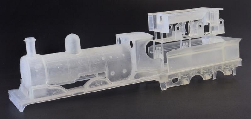
Photograph AJModels
The kit is supplied as a single unit, as per the photo, and the loco and tender have to be separated, as have the components provided as part of the tender print. This comprises the tender body (bottom), the underframe and the coal bunker insert. Included in the joining spruces are six loco brake blocks and hangers; a tool box for the tender and the reverser.
The parts were separated, and the loco and tender elements given their first coat of grey primer, as per the instructions.
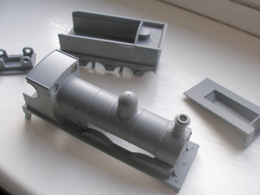
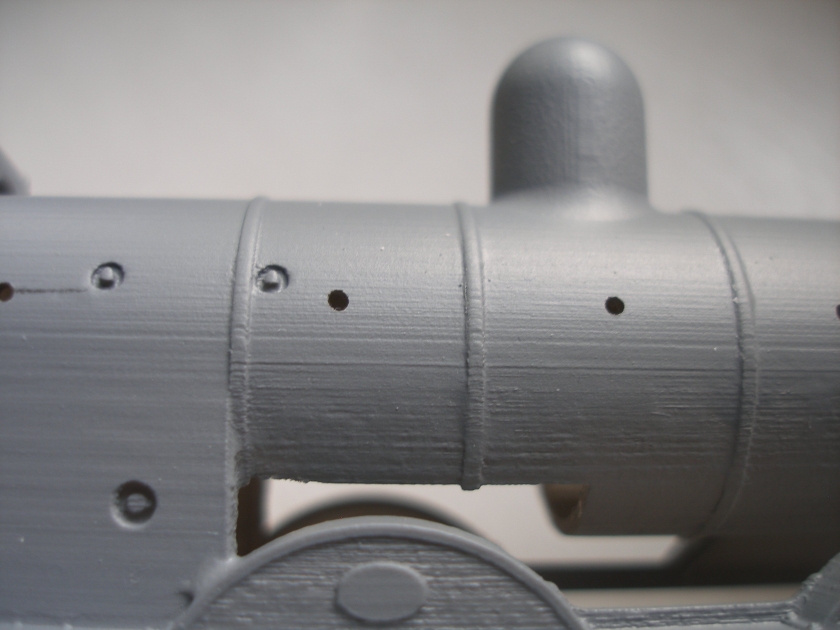
The 3D printing process creates a series of ridges, which can be seen clearly in the photo below. The recommended rubbing down with wet-and-dry has not yet been done, but the holes for the hand rail knobs have been drilled. The holes may seem a little oversized, but I find if I make them smaller, I cannot get the knobs into them.
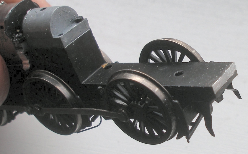
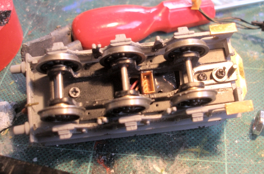
The donor chassis requires the first 3mm to be cut from the front of the chassis block, as shown below. I cut mine and then filed it till I got nice fit. Looks as if i might have bent the coupling rod.
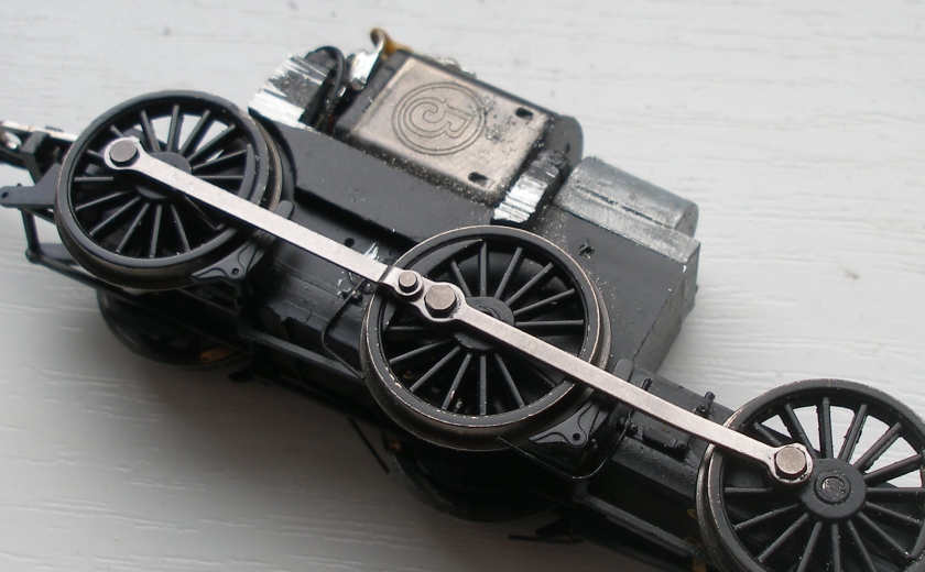
There are two small ridges in front of the motor which also have to be filed off; it is nt immediately obvious what these are for. The photo was taken mid-process.
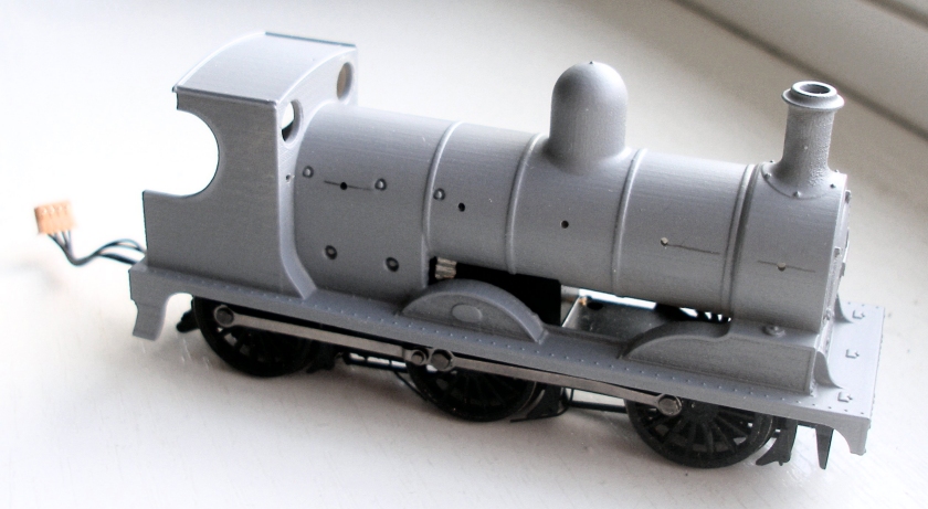
And it fits!
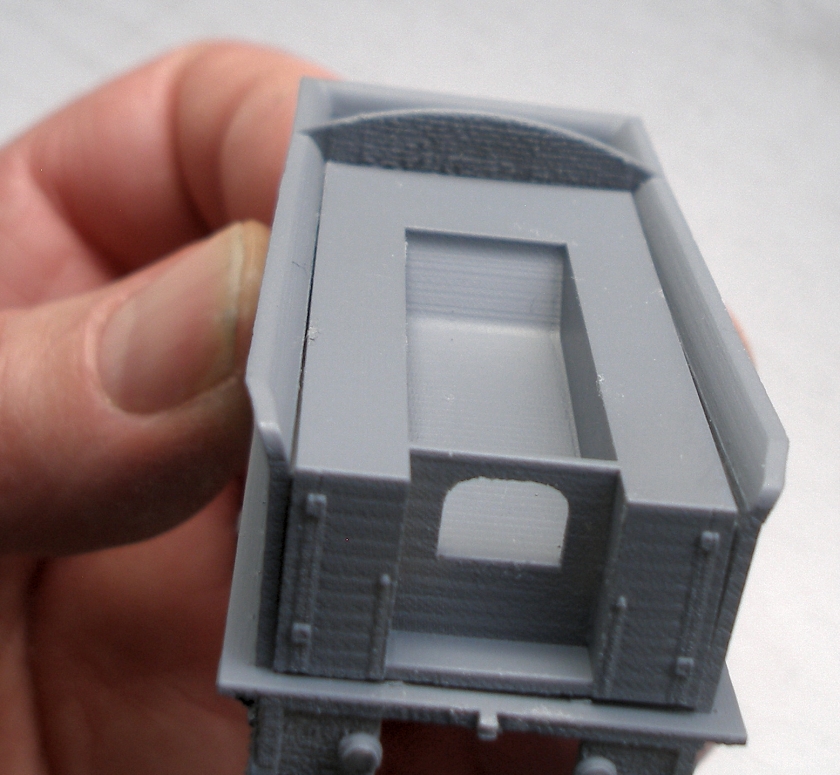
The tender elements were also assembled. Although not immediately obvious, I failed to appreciate how brittle the material was, and broke off the left hand side panel of the tender when rubbing it down. It was possible to superglue the broken section back in place, but care does need to be taken. In retrospect I should have rubbed the tender down with the insert in place.
Various bit and pieces were ordered from Alan Gibson (excellent customer service with very speedy delivery). This is the list of parts ordered:
1 x 4902 Lancashire & Yorkshire type buffers Price U (4 buffers required) £5.50
1 x 4M53 25 x Handrail Knobs (short) Price AB £7.30
1 x 4M54 25 x Handrail Knobs (medium) Price AB £7.30
1 x 4M65 10 x mainframe bearing bushes for 2mm axles Price E £2.50
3 x 4842 3' 6" 14.0mm. 10 spoke Plain £3.10 = £9.30
1 x 4M136 10 x 10” lengths of 0.45mm. brass wire Price K £3.70 £7.40
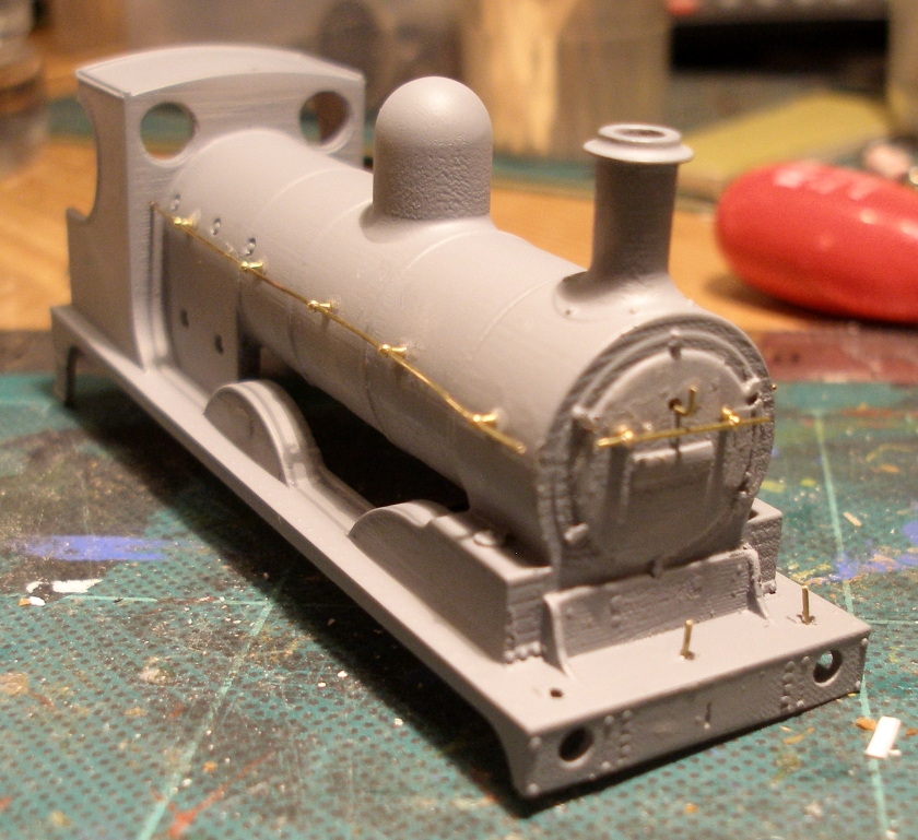
The handrails have now been fitted. It is apparent that a short handrail knob should have been used on the smoke box.
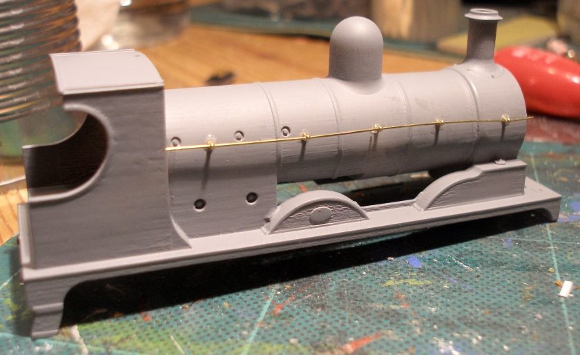
The
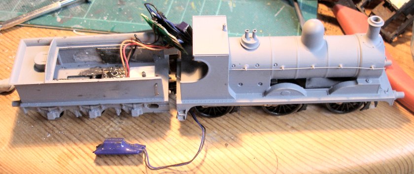
The tender body chassis was removed, and photo below shows the DCC socket, the PCB which is wired to it, and plugged into it a Zen decoder and then in the distance, the stay-alive.
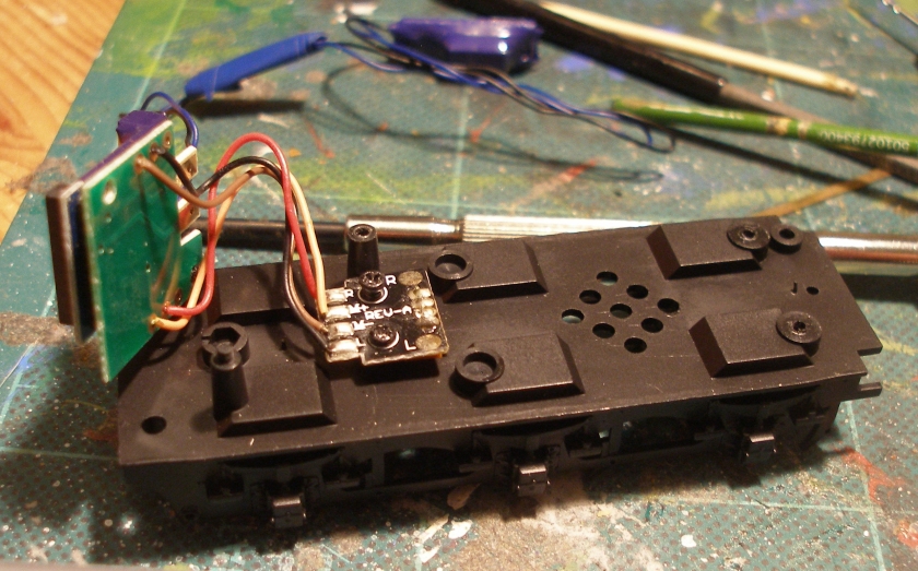
The decoder PCB was taped up and then tried in place on top of the inner tender frame.
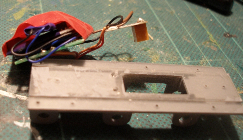
When the Alan Gibson tender wheels and bearings were fitted to the inner tender frame, it was apparent that material needed to be removed from the top of the frame, as shown in the to photographs below.
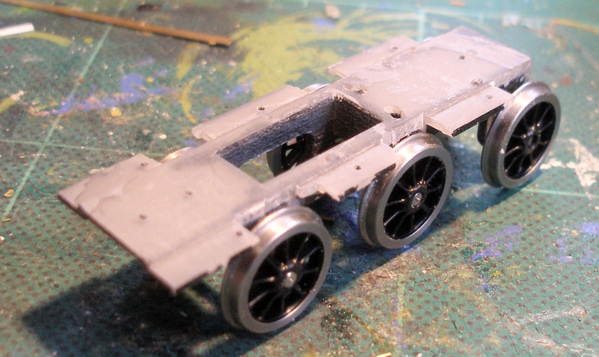
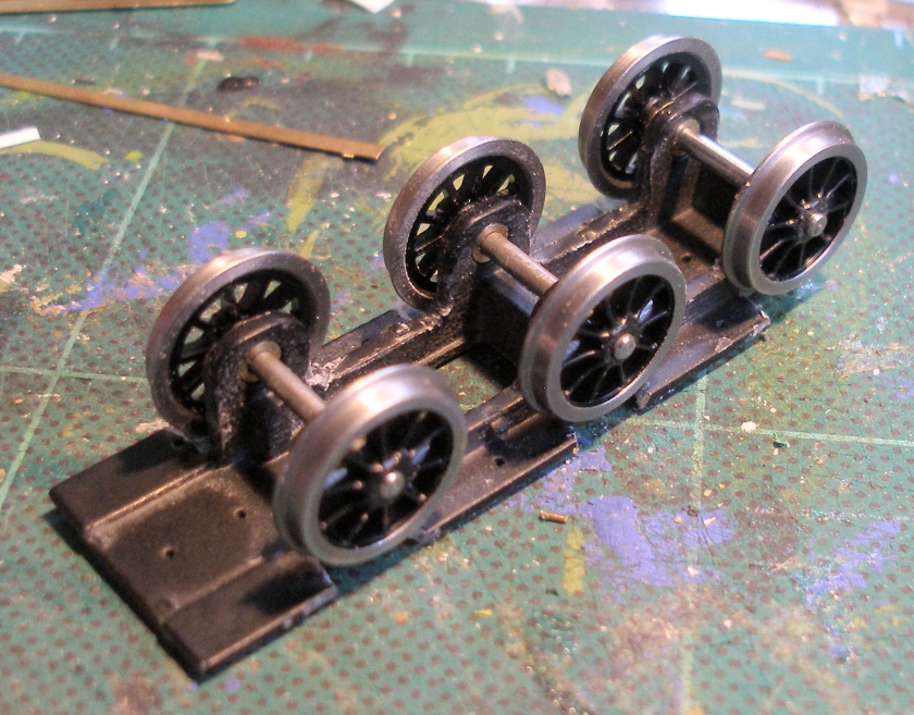
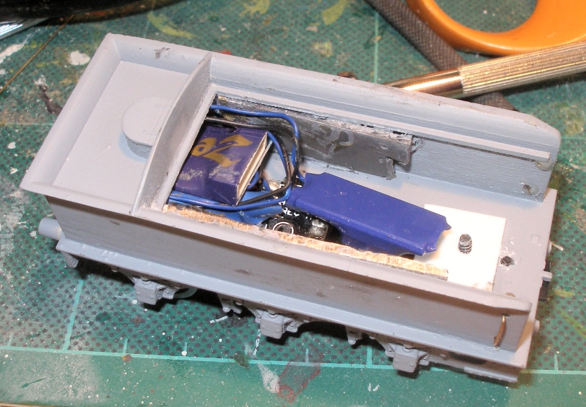
The body and inner frame were united, and then the Zen decoder carefully inserted into the water tank space. The socket in the base of the tender is shown with the soldered tabs facing the rear of the tender. This neatly allowed the Zen stayalive to fit into the slot in the base of the tender/inner frame. However, I concluded that the plug needed to plug in the other way, and so this neat arrangement didn't work, but the stayalive could lie on top of the decoder, at the back of the coal space. Note that at this stage lead has been glued to the inside of the tender sides. The short piece of lead on the driver's side was with the idea of leaving space for the stayalive if needed.
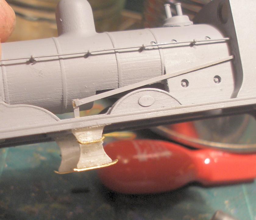
Back to the loco, and Andrew recommends using translucent packaging to form the steps. I thought these would be very vulnerable, so opted for brass. I had set of Comet Stanier footplate steps handy, and thought I could cut two slots in the cab steps.... The first hole has been drilled.
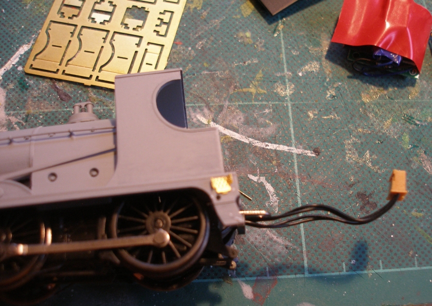
The brittle nature of the material has already been noted, and the tender step broke off as I opened up the first slot. It turned out to be easier to form the slots once the steps had broken off (!). However, the treads were fitted, and the steps successfully reassembled. I reinforced the back of the two steps using JB Weld. The well-known Horwich photo archive held by the National Railway Museum has a wonderful photo of the Class 27 cab taken from track level (with the tender still to be coupled up) and shows these steps are supported by a stay, so I felt reinforcement in this area was clearly prototypical.
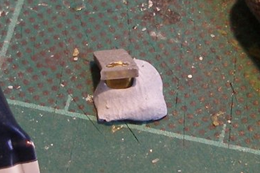
The tender coupling spigot has been fitted, and as can be seen from the screws poking trough the floor, the inner frame screwed to the tender body. The DCC socket has been reversed, and now the DCC gear is ready to be poked into the water space at the back of the tender.
And finally it is time for the first test run. She has just crossed from the Up Calder Valley main line to the Down line using the cross-over behind the tender.
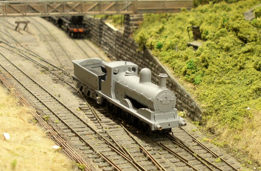
At this point the weight from the Class C had not been fitted in the Aspinall boiler, ad it is also apparent that the tender is going to need its weight doubling.
The cab handrails were fashioned from scrap brass and .45mm straight Gibson wire.
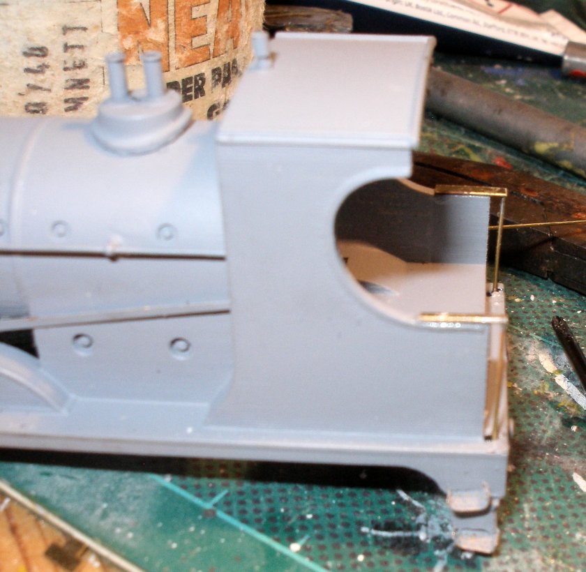
The instructions suggest using the Class C fall plate, but I had a spare one from an old kit fret.
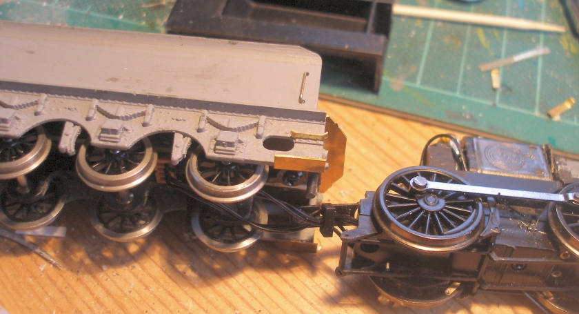
The brass treads have now been fitted to the 3D-printed steps, which in turn have been glued to the underside of the footplate. The reversing rod formed from brass scrap is joined rather crudely, and rewarded me by breaking whilst I was fiddling with the steps! So was re-affixed after this photo was taken. The bottom step has greater depth, and is glued to the bottom of the step, rather than being glued to the side.
Finally, the tool box has been added to the top of the tender.
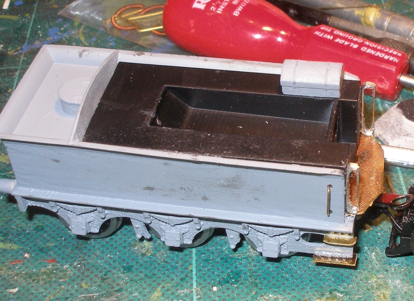
Flipping the tender over, the re-used Class C loco coupling spigot can be seen, screwed to the tender frame.
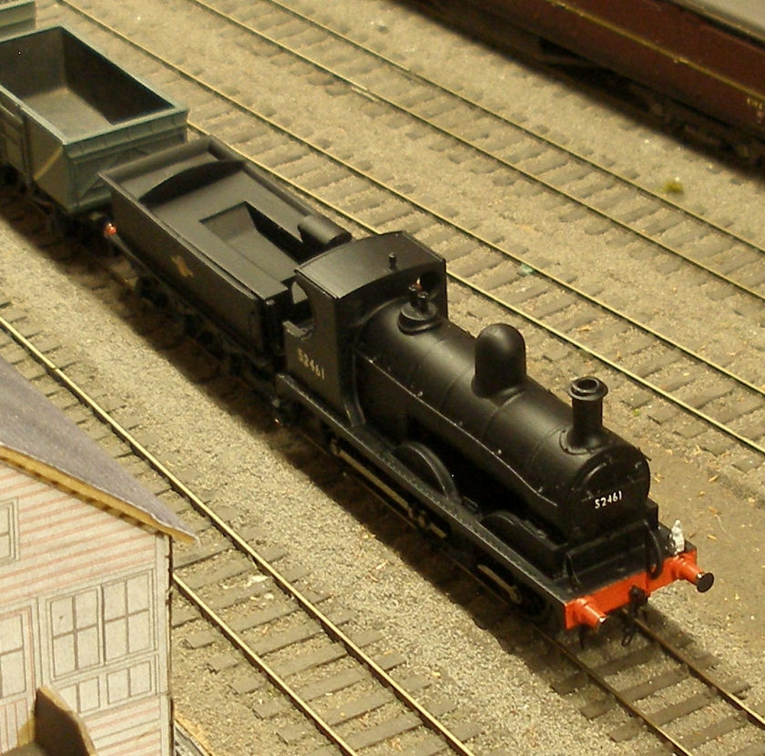
A couple more days and the Matt Black car spray has had an outing. The front coupling from the Bachmann Class C has been successfully grafted onto the front buffer beam (a K's/W&H/Romford screw coupling has been fitted to the back of the tender). Note the Springside BR headlamp on the right hand lamp bracket denoting a pick-up freight working.
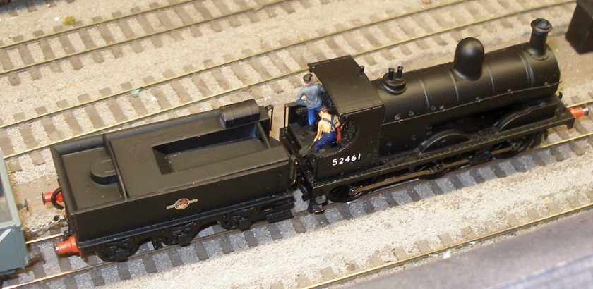
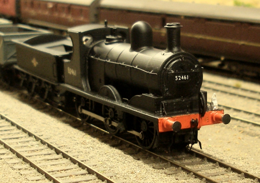
The smokebox number plate was formed from numbers cut from Fox transfer sheets.
