
A 'free' bogie tender for a K's Black 5
The K's kit was a good model, although was ultimately overtaken by the DJH kit which included more etched parts, including an etched tender top - the K's tender being totally formed from white metal castings.
The tender has two primary faults: it is very heavy, and the lips of the coal bunker / top of the tender tank are overly thick. The first thought was to replace it with a more recent etched version or a spare Bachmann/Hornby one sitting in the spares box.
However I have previously used the system where only the rear tender wheels actually carry any weight and the middle and front axle sit in a non-weight carrying 'free' bogie. The front of the tender is coupled to a central spigot on the loco, as with a caravan when towed by the ball socket under the rear bumper of a car. This allows the front of the tender to be packed with lead and so contribute to the adhesive weight of the loco. This produces a better weight distribution when the front of the boiler is also filled with lead. I had also found that tender set-up like this runs very steadily at speed in reverse with virtually no risk of derailment. And the extra weight on the rear tender wheels also makes them an excellent set of wheels for an extra set pf pick-ups.
The entire project took about 90 minutes. This is how you do it...
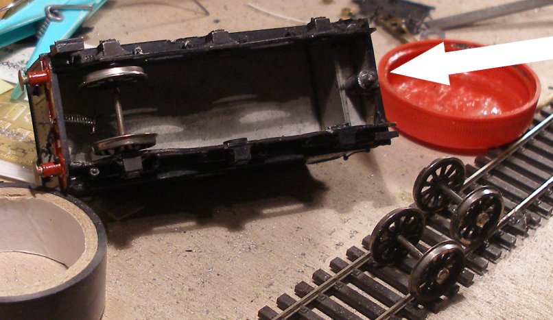
First, the front and centre wheel sets were removed. As this tender is solid whitemetal, the frames had to be gently parted to work the axles out of their holes. The axles were of the old rounded-end style, so there is a further benefit in replacing these friction-friendly bearings. The axle ends have been cut over with the cutting disc. The rather clumsy spigot forming the tender coupling is arrowed, which the tender will pivot on.
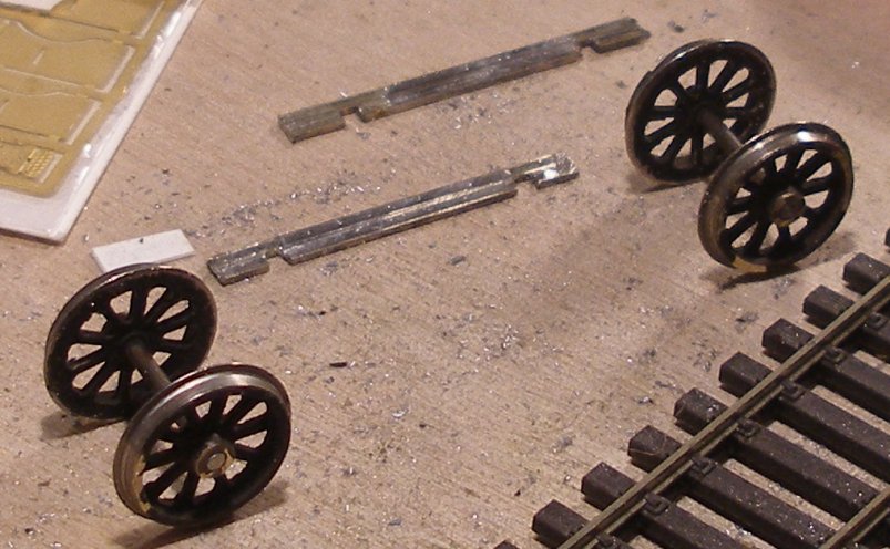
The frames for the floating bogie were created from lengths of bullhead rail soldered together.
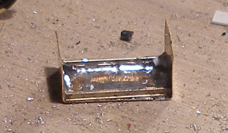
A top for the free bogie was created from a spare piece of brass, and strengthened internally with further pieces of rail soldered inside.
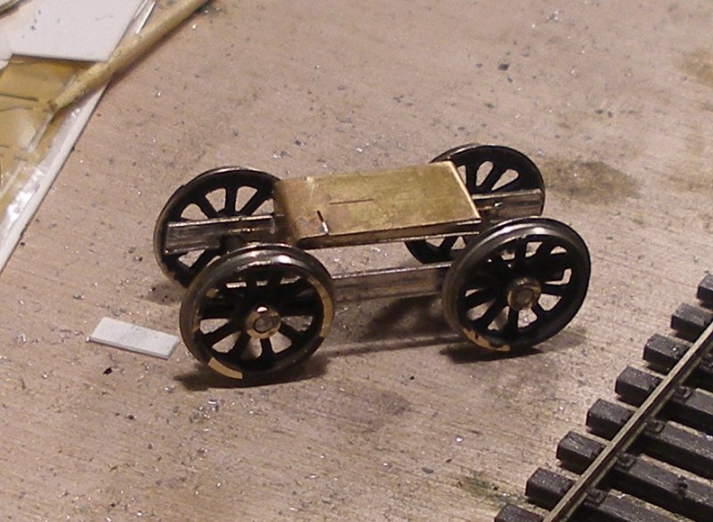
The top and frames of the free bogie are united.

A hole was drilled in the top of the free bogie for the bolt. A stretcher is shown with the bolt soldered to it, ready for fixing inside the tender on the ledges formed by the frames with superglue.
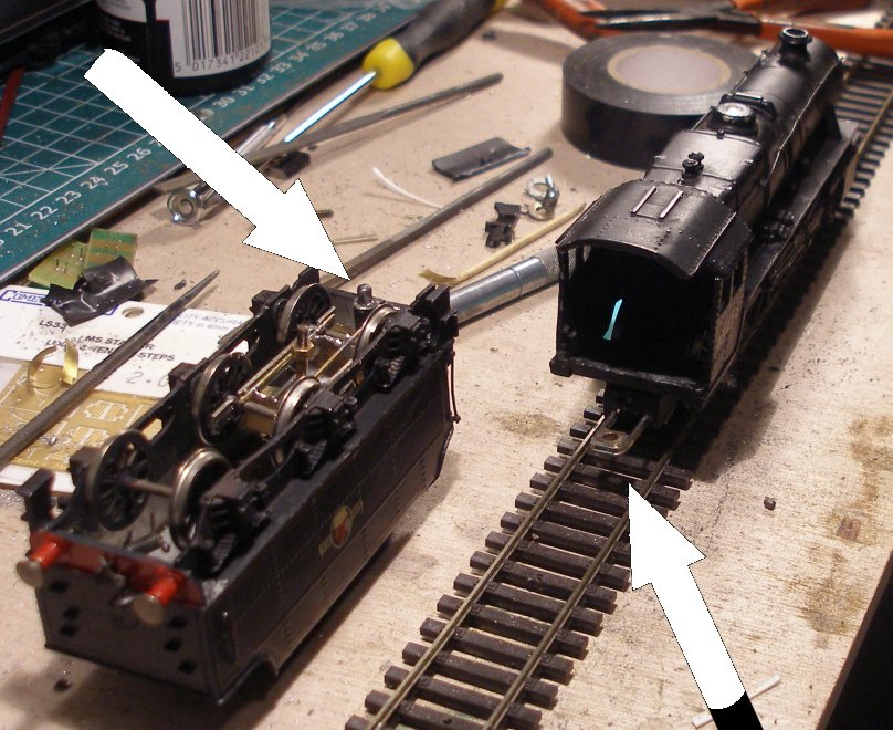
The tender and loco are now ready to be connected. The spigot on the tender is arrowed, as is the rear drawbar attached to the frames of the loco in which the spigot will engage.
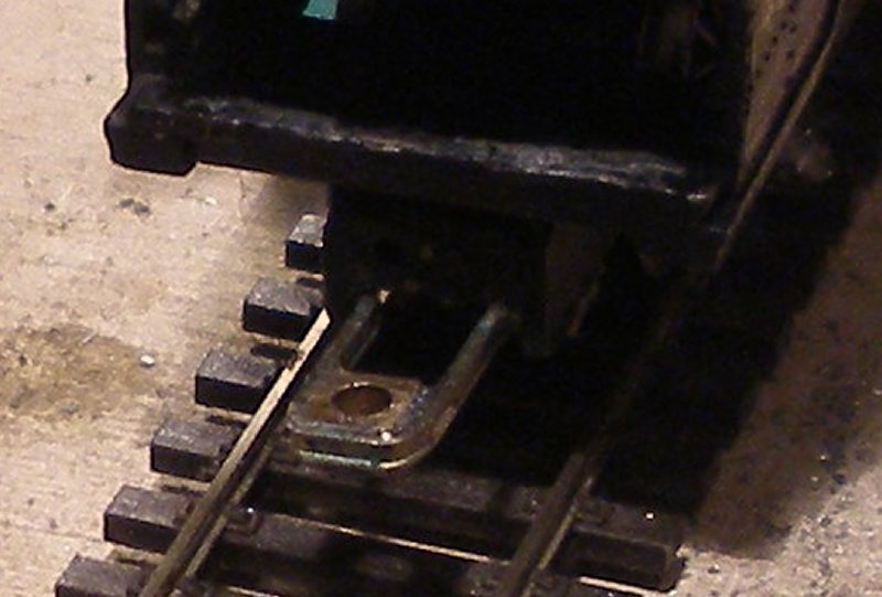
The rear drawbar on the loco is formed from a spare loco axle box and more bullhead rail, which in turn is soldered to the brass frames of the loco chassis. As the front of the tender is entirely supported by the drawbar it has to be rigid, capable of supporting the weight of the tender and the height checked with the tender attached.
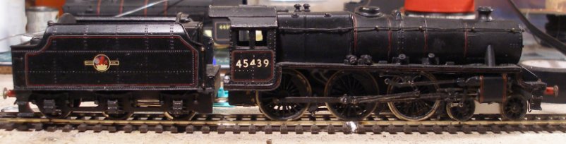
The finished Ks Black 5 with free bogie tender attached, making for a very heavy loco with plenty of adhesion weight where it is needed. Note how by creating a 'bridge' there is daylight through the first cutout in the tender framing. The fallplate will now have to be hinged, as it will have to be raised to allow the tender to be uncoupled. At the start of the process the cab and tender steps were in place, but were knocked off as the job progressed. However, as will have been observed in the photos, a set of Comet steps is handily lying on the workbench. A set of cab doors would also help fill the gap between cab and tender. Wonder why the BR crest is off centre on the tender?
Click here for the genesis of '45439' - from eBay 'spares or repair' to 'steam to spare' in 40 minutes: new life for an old K's Black 5.
Copyright J K Wallace, t/a 'Hall Royd Junction' 2013-2023 email: Hall Royd Junction
7 Portobello Close, Chesham, Bucks. HP5 2PL, UK
tel: +44 (0)7513 412880