
<<< Signals for a model railway Sharge Track Cleaner >>>
Fried sound chips
Chipping a fleet of DCC locos is a time consuming task, particularly when many of them are kit built. The long term ambition is to have a sound equipped fleet, so it is with great disappointment I have to record the demise of half of the Hall Royd Junction sound-fitted fleet.
Our Black 5 was sitting on the 'main' - but not selected - when there was a loud 'crack' and a whiff of burning. The sound and the smell suggested the Black 5.
It still ran beautifully smoothly for and aft, but without sound :-(
A call to Hornby's technical support suggested that it was the speaker, and one was obtained for the sum of £6.
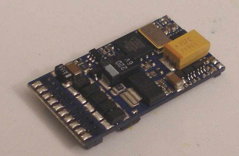
Suffice to say, as the photo shows below, it wasn't the speaker.
These are not easily obtainable spare parts and we await Hornby's response to our e-mail (16 November 2014) is now awaited.

Our other (now only) sound-fitted loco is the Bachmann 37. We haven't investigated but believe are both equipped with ESU V 3.5 chips, so it follows if one has 'blown', so could the other.
Without knowing the cause of the surge or whatever that caused the chip to blow, the remaining sound-fitted loco is now stored off the 'main' when not being used.
However, Hornby's customer service was... outstanding, and the story has a happy ending.
A further e-mail to customer service led to a request for a photo so that the correct replacement chip could be identified, and Ken at Hornby confirmed that it was a version 3.5 LokSound decoder... Ten days later the chip shown below arrived in the post.
Well done Hornby! Customer service as it should be.
9 February 2015:
In early February Howard Greenwood called to say he had an identical occurrence, with the loco sitting on the main but not selected, and the chip 'exploding'. Howard did not subsequently test the loco to see if the chip could still be used conventionally (that is, to power a loco but without the sound).
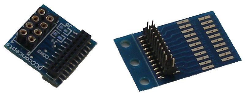
Fitting a 21-pin chip to an 8-pin socket is problematical, as the conventional wisdom is to fit an 8-pin chip to a loco with a 21-pin socket, and to this end DCC Concepts has created a converter (shown on the left in the image below). One was acquired to see if it would interface an 8-pin socket with an 21-pin decoder.
It did not look promising, but an e-mail to DCC Concepts elicited the response that there was little demand for such an item, but they had created a 21-pin board/socket intended for those converting non-DCC fitted locos to DCC and wanting to installed a 21-pin decoder.
So it is a socket which has to be soldered into the loco, but crucially the 'spare' 21-pin chip can now be fitted. For those needing such a thing, it is correctly described as an ESU 51967 Compact universal 21MTC adapter board for LokPilot/LokSound V3.0 and V4.0. The instructions note you can: "Hard-wire this adapter into your locomotive and all Decoders with 21MTC connectors (ESU LokPilot or LokSound for example) can simply be directly plugged into it. A neat way to create a perfectly tidy install when there is room available, as it allows integration of speaker wires too". The board is shown on the right in the image below. Details are here.
With the spines uppermost, here is a diagram showing which wires go where: this had been deduced from other diagrams posted on the Web: I only need the track and motor supplies so you are advised to double check that these wire colours match your intended functions, as there do appear to be a number of variations by manufacturer. I would have checked my own sound-fitted locos but rather unhelpfully they feature black wires throughout. The board is designed to have the wires soldered on to it from either side, as both sides are numbered.
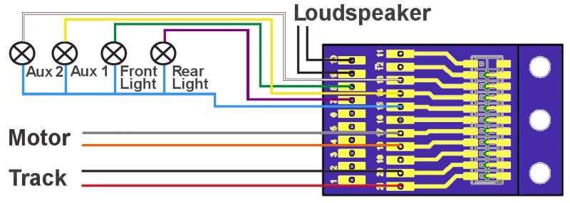
The motor wires go to tabs 16 and 17, and the wires to the track to tabs 21 and 22. For orientation purposes, note that the 'missing' pin is in the top right hand corner.
But now here is the rub, as the photo shows, with ESU adaptor alongside a sound decoder, there is a mismatch of pins; both being in the same plain, with the 'blank' pin being to the right on both chip and adaptor, meaning that they can't be plugged together. Clearly clarification is required here. Who said DCC was 'just' two wires?
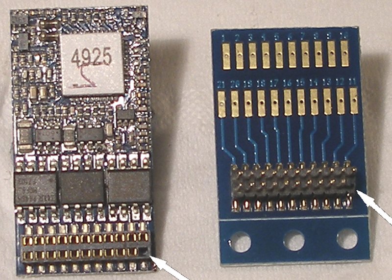
Working on advice received from the Yahoo! DCC Group, I am advised that the decoder and adapter plug together exactly as seen, with the decoder being rolled over to the right to meet the adapter, so that effectively two pins are effectively blind. The following photo log shows th process of fitting the adapter and 21-pin chip to a Portescap-fitted DJH Caprotti BR Standard 5.
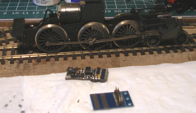
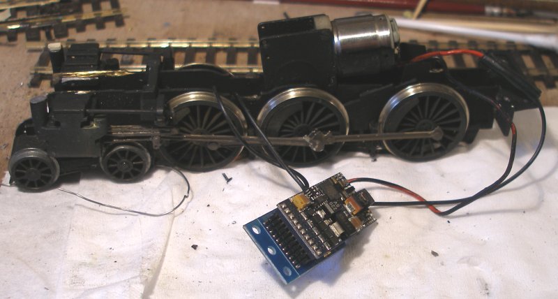
The DJH Caprotti Standard 5 Portsecap-fitted chassis with the body removed on the workbench with adapter and 21-pin chip in the foreground.
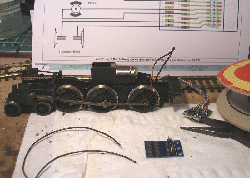
The DJH Caprotti Standard 5 Portsecap-fitted chassis with pick-up wires pulled through ready to be cut.
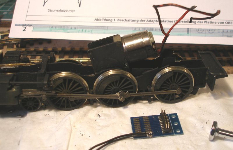
The chassis with pick-up wires cut, and the new pick-up wires soldered to the adapter. Note the ESU wiring diagram propped up behind.
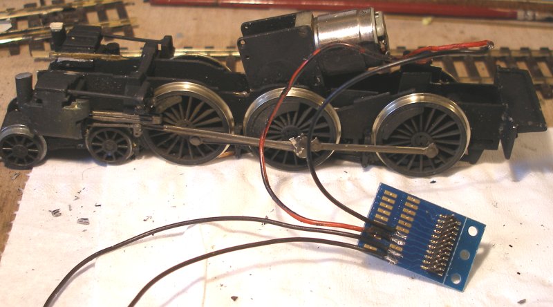
The DJH Caprotti Standard 5 Portsecap-fitted chassis with pick-up wires and motor wires soldered to the adapter.
The decoder now plugged into the adapter plate. Note how the decoder is located in relation to the adapter plate, so it is literally on top of it.
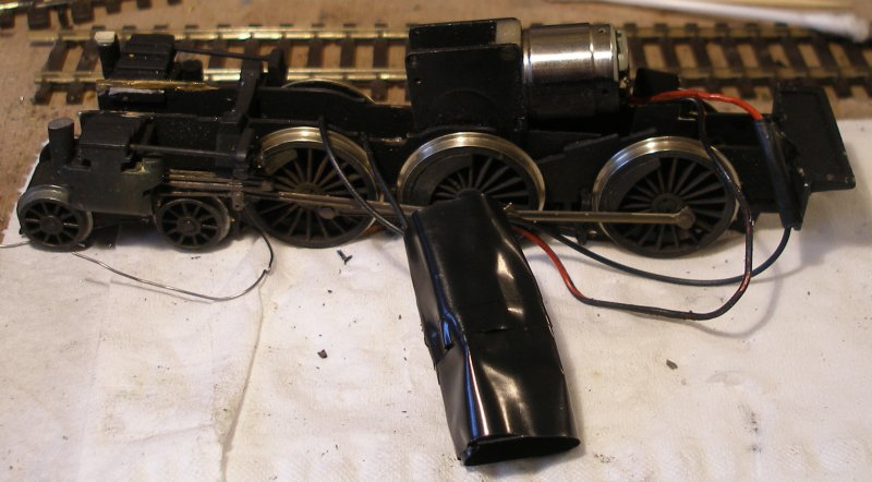
Now the 21-pin decoder and adapter plate is wrapped lightly in insulation tape ready to be inserted into the whitemetal boiler barrel.
And now an admission: having got this far, it didn't work! With the decoder plugged in, there is a short. Lots of possibilities, including wiring the adapter plate incorrectly and the chip having blown. Further investigation required.
Posted 29 February 2015
Cheap as chips - assessment of a low-priced decoder from Hong Kong A new page has been created dealing with the laisdcc decoder.
Copyright J K Wallace, t/a 'Hall Royd Junction' 2013-2023 email: Hall Royd Junction
7 Portobello Close, Chesham, Bucks. HP5 2PL, UK
tel: +44 (0)7513 412880