
<<< Workshop for a model railway layout Readying a DJH Crab >>>
Tales from the workshop: DJH WD 2-8-0 restoration
Focus has now turned away from the layout for a while whilst a strategy for dealing with the large collection of 'spares or repairs' eBay 'treasures' are tackled.
These were all bought because they looked like quality kits that had fallen on poor times for one reason or another. And with the ever growing number of quality ready-to-run models pouring out of the Chinese production lines of Bachmann, Hornby and Heljan it seemed possible that these models would find there way back onto eBay in their original, unrestored forms.
Two events have brought about a change in direction: the surprising lightness of some models (not a fault of Heljan) - and therefore their lack of traction and pulling power; and the slowly rising cost of the newer models. So the tide has turned in favour of the collection of models awaiting restoration.
The first to be tackled in the new regime was a DJH WD 2-8-0. When bought 10 years ago it arrived coated in what looked like Dulux Black Gloss. It ran smoothly in both directions but the motor - one of the small open-framed type (a DS10?) - had not grunt and the wheels would stop turning if the loco was held with power on.
The first step was to strip off the old paint. This process was quick, and effective, but unfortunately the loco was glued rather than soldered and all the small parts can off at the same time. Other projects and priorities took precedence, and this particular 'treasure' has sat in its box for the last 10-years.
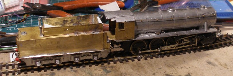
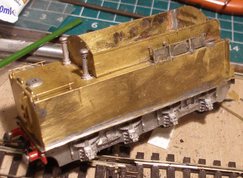
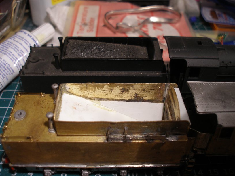
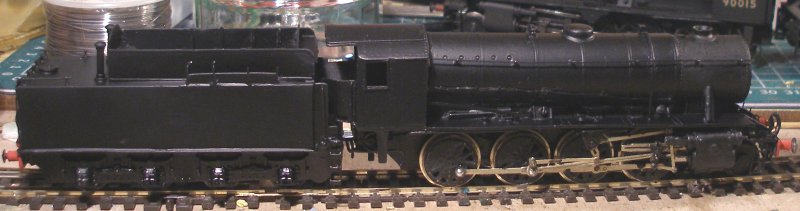
The loco has been on the work bench for 10-days or so. The buffers and buffer beams have been re-attached, and a new tender drawbar fitted. The tender is surprisingly heavy - possibly heavier than the loco. There are three cast whitemetal structures within the tender: the chassis unit; the inner coal bunker and the tender front bulkhead/lockers. A decision was taken to lighten the load, and the coal bunker was removed and replaced by a plasticard replacement. The top of this replacement can be seen inside the coal space. The front bulkhead casting is surprisingly heavy I was in two minds whether to replace this as well - for now, it is staying.
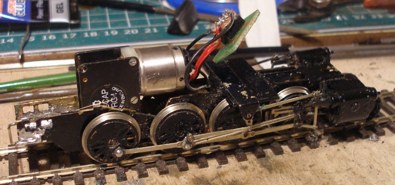
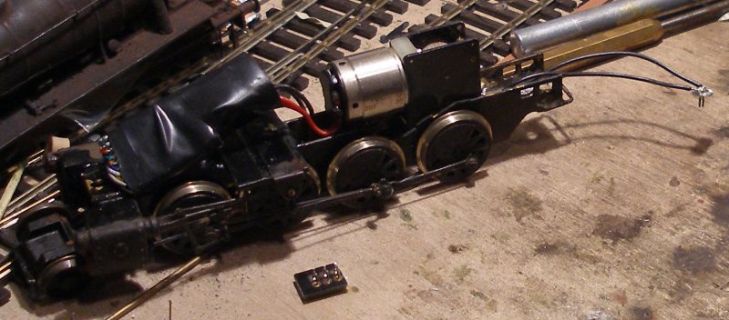
The shot shows the an RG4 motor fitted and tested. I had hoped to fit the motor vertically, but there was insufficient room. The DCC socket has been fitted, with the Hornby blanking plate in place, and wired to the pick-ups to allow it to run up and down the test track. The plan is that the socket - and eventually the DCC decoder will poke down the empty boiler barrel. The remnants of the gloss black can be seen on the motion bracket and cylinder block.
The DS10 motor had been fitted in a gearbox, but there seemed no reason to remove the old gearwheel, as this would have meant removing the cranks, etc. The remains of the old gearbox were carefully removed with a cutting disc. New wires were required from the pick-ups and chassis to the DCC socket.
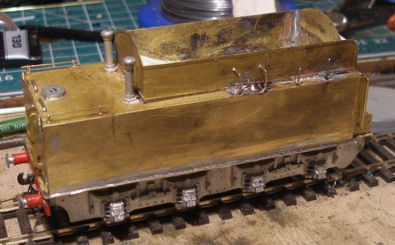
The tender has been reassembled but still needs a bit of cleaning up. New handrails have been fitted on sides of the rear tender apron using medium handrail knobs. The pair of handrails at the rear of the apron are how she came, and this will be replaced with something thinner. The fire iron racking on the tender side is being created although the solder is looking a little lumpy at present. The tender steps are not currently fitted, and these are being reviewed as the DJH items do not really reflect the prototype. There do not appear to be any commercial WD parts, but examination of YouTube videos suggest that the steps from Ivatt Classes 2 & 4 might also be suitable.
Posted 15 December 2014
The focus continues on the tender. I had always assumed that the fire iron rack on the tender was formed of 4 upright rods, but a study of the YouTube videos of the captive 2-8-0 on the Keighly and Worth Valley Railway showed a steel sheet welded to the uprights. Further study of the prototype in BR service showed this to be a standard feature. A suitable piece of nickel silver was found on an old fret.
The WD 2-8-0 tender showing original rear hand rails formed from thick wire loops. Study of photos shows that this detail would be formed from long hand rail knobs...
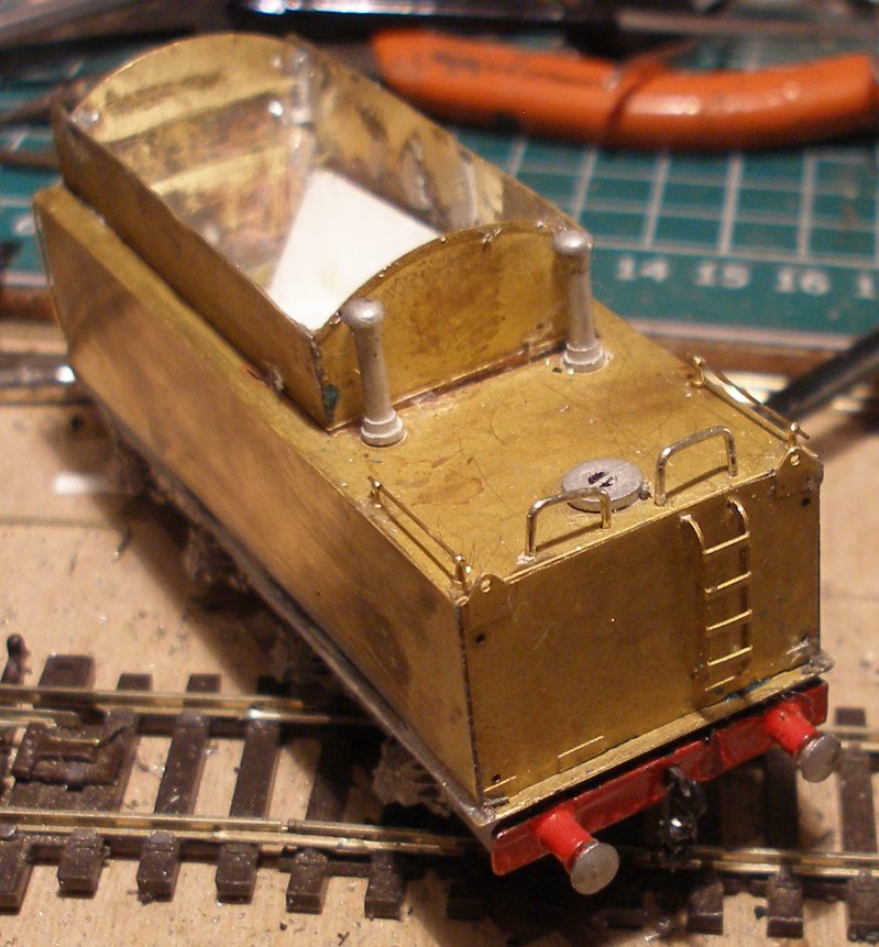
Now with new rear hand rails fitted using hand rail knobs. Photos seem to suggest the left hand one protrudes from either side of the knob/stanchion whereas the right hand one above the ladder is shorter. The two long vertical handrails on the rear tender sheet have also been fitted, although the right hand one needs straightening. There is an obvious gap above the buffer beam which will need sorting.
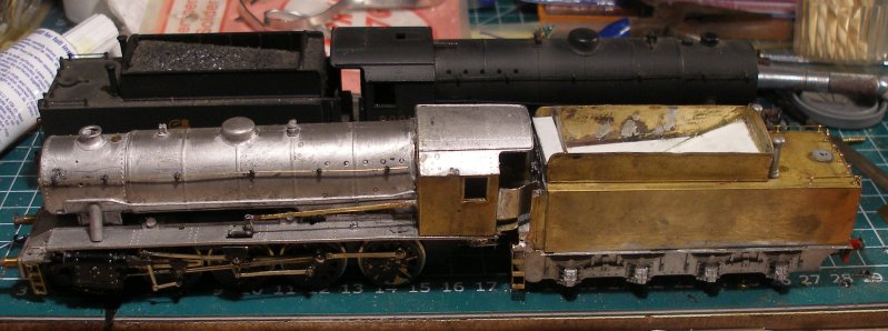
The lubricators and sandbox fillers are now back on the running plate. Behind is the Bachmann model. Interestingly the Bachmann tender lacks the fire iron rack, whereas the DJH model lacks the ribs inside the bunker. In this view the cab doors have been fitted - a curious omission on the Bachmann model. The new doors have been fashioned from a set of frame spacers taken from an old chassis fret.
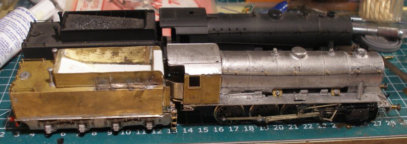
A close up of the two tenders
A shot of the other side of the loco shows that the reversing level has been fitted.
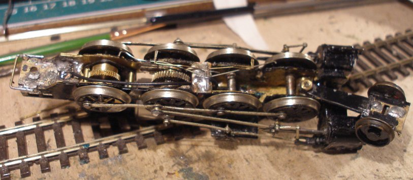
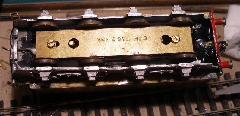
A shot of the under-side of the tender shows the relative crudeness of the chassis.
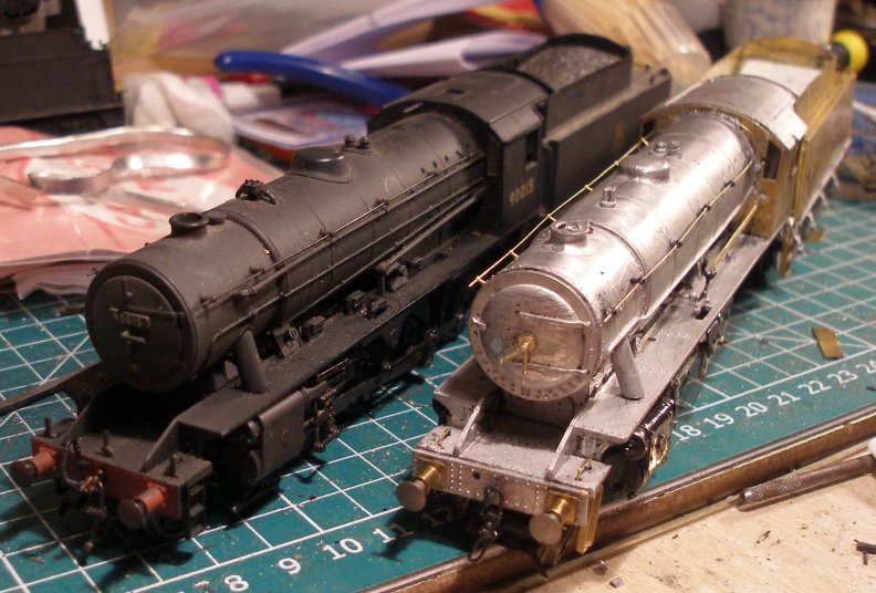
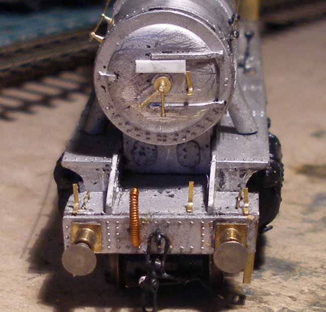
This front view shows the smokebox handles have now been upgraded with a set from Markits. The original was a crude cast job. The DJH model does not feature a numberplate, which will have to be fabricated.
Posted 22 December 2014.
<<< Workshop for a model railway layout
Lamp brackets are clearly missing the DJH model. I found some Shawplan brackets that fold up from a brass etch, but opted to make mine from a spare fret of boiler bands. A smokebox number plate has also been added.
DJH WD 2-8-0 4mm scale model showing smokebox and footplating with lamp brackets added.
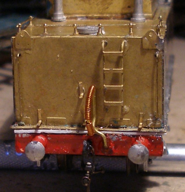
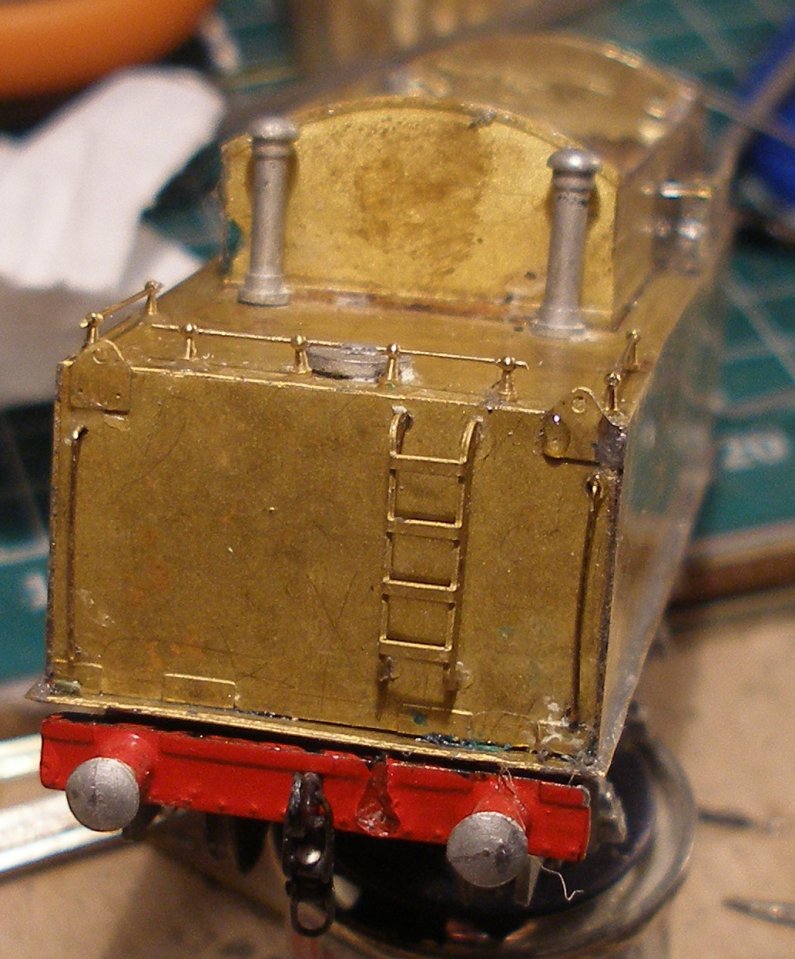
DJH 4mm WD 2-8-0 4mm scale model showing tender rear with lamp brackets added.
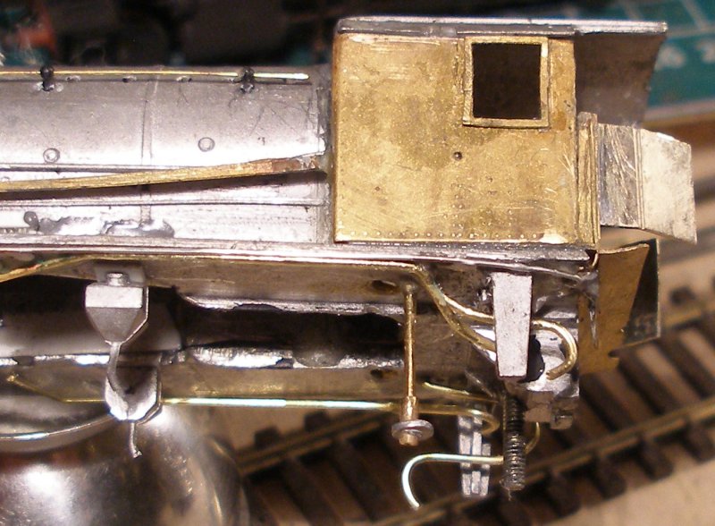
On the fireman's side a series of pipes are routed down the outside of the boiler cladding, which appears to end in a casting of some sort - no detailed prototype snaps available of this feature - so for now the pipes have been routed over the top of the frame. The brackets have been formed from the boiler cladding etch and the piping from 5 amp fuse wire. DJH cast this piping onto the boiler side but it is understated and too low down. The photos show the first attempts to gentle remove it with a craft knife.
The rod on the fireman's side has been added but had to be lengthened. Also the cladding for the top feed, together with the vertical pipe exiting through the footplating has been added. The narrow firebox was an issue for the Portescap RG4 motor and gearbox, and much material had to be removed from the inside, such that a hole formed at the bottom of the firebox cladding. This hole has now been filled with plasticard, as seen in the photo.
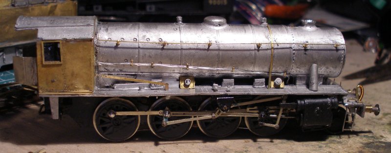
DJH WD 2-8-0 4mm scale model showing fireman's side with a series of pipes routed down the outside of the boiler cladding, which appears to end in a casting of some sort - no detailed prototype snaps available of this feature - so for now the pipes have been routed over the top of the frame. The brackets have been formed from boiler cladding and the piping from 5 amp fuse wire. The rod on the fireman's side has been added but had to be lengthened. Also the cladding for the top feed, together with the vertical pipe exiting through the footplating has been added. The narrow firebox was an issue for the Portescap RG4 motor and gearbox, and much material had to be removed from the inside, such that a hole formed at the bottom of the firebox cladding. This hole has now been filled with plasticard, as seen in the photo.
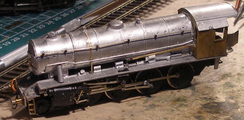
DJH WD 2-8-0 showing driver's side with reversing lever added and substitute lubricators formed from plasticard and fusewire. The reinforced lifting holes have been drilled through.
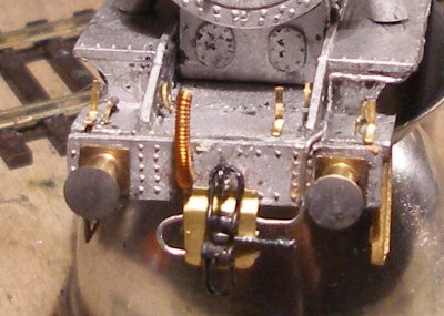
Front end of 4mm DJH WD 2-8-0 showing piping and bang plate for AWS.
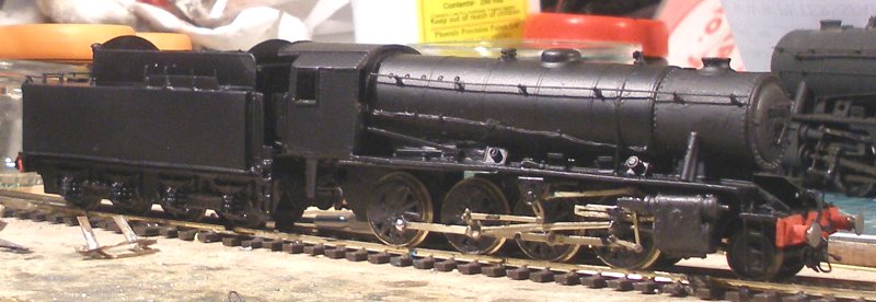
The model is now ready for its first undercoat, and the last two shots show the bufferbeams masked off, and the tender after its first coat.
Meanwhile the chassis has been chipped and has been running on the layout. The fireman's side cylinder however fell off. Inspection showed it had been glued on originally. Some long-curing Araldite left to set over night has cured the problem.
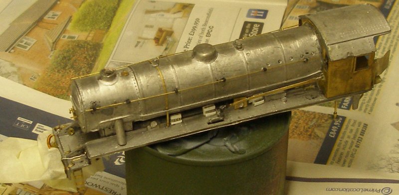
DJH WD 2-8-0 ready for undercoat.
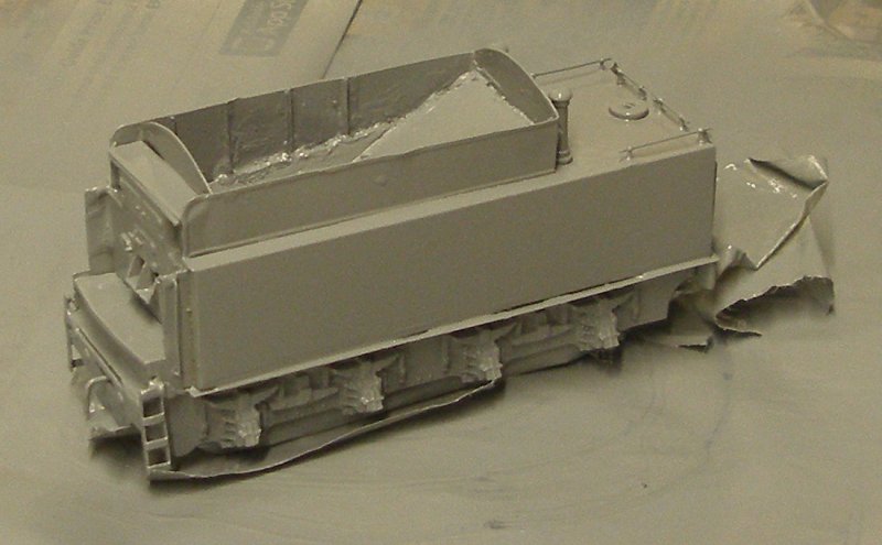
Tender of DJH WD 2-8-0 with its first coat of primer.
There are some obvious defects where the tender top joins the footplate, and so a bit more work with filler and 'wet-and-dry' is clearly required.

DJH WD 2-8-0 after undercoat has been applied, and with some imperfections still requiring correction, notably on the firebox sides above the piping, and on the tender side below the fire iron shelf. The cab window frame is also looking a little odd. This illustrates the importance of using a coat of undercoat to show-up any defects, which are further accentuated in the photographs. The taking of photos as the job progresses has allowed a number of defects to be identified as the work progressed, which I didn't spot on the workbench.
Posted 14 January 2015
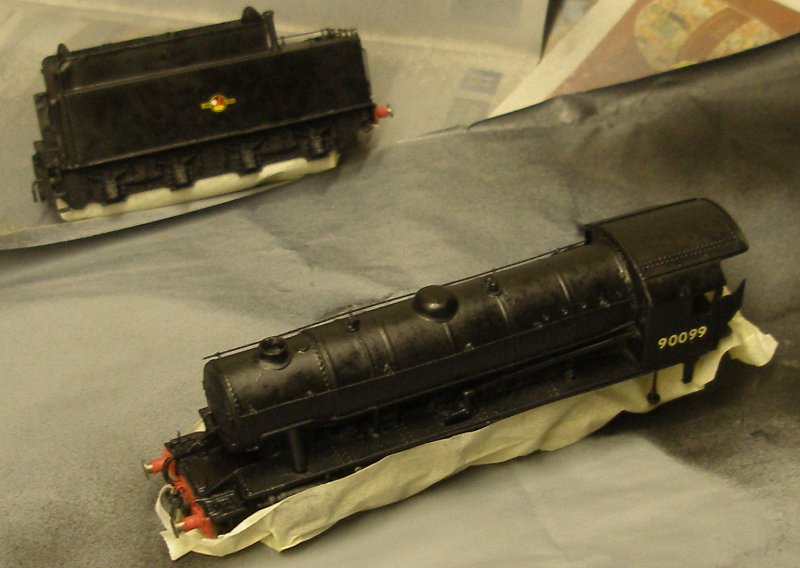
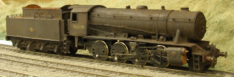
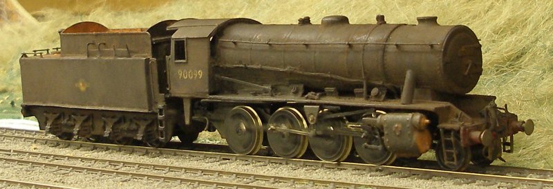
The paint shop reveals a very clean black locomotive now awaiting BR crest and numbers - 90099 is a likely candidate.
Posted 16 January 2015
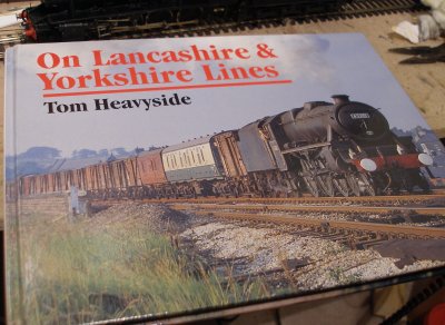
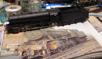
The critical question is now to choose an identity. I have found Tom Heavyside's 'On Lancashire & Yorkshire Lines' an invaluable aid, and the photo of 90099 at Goole in 1965 fits the bill nicely. Note the lowered lamp brackets and AWS fittings which mirror our own loco...
Posted 17 January 2015
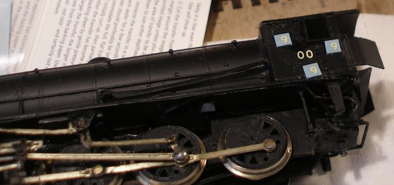
The livery of the WD is about as basic as it gets: a set of numbers of the cab side; a smokebox number and shed plate, and an emblem on the tender. This shot shows that the track gauge is proudly displayed - only joking. The transfers will form '90099'. As seen in the photo, I initially used the smaller set of numerals contained on the Fox sheet, but then realised from the Bachmann model and the photos available that the WDs had the larger size of numerals.
Finally, a coat of Precision matt varnish was sprayed onto the finished model. It was obvious that the varnish wasn't spraying evenly. A quick 'Google' found an RMWeb discussion suggesting that varnish should be sprayed in a warm room - I tend to spray in the loft when was distinctly cool this afternoon. The loco and tender have now been placed in a warm room and we'll see how it dries...
Posted 18 January 2015
In the end the varnish dried with what could be described as a Cloudiness or Blush, which is just apparent in the photo above. The good news it hadn't crazed the paint, and looked capable of taking a brushed coat of Humbrol matt.
I found this article at http://www.info-central.org/?article=314 very helpful - scroll to the bottom of the page for a helpful table. Other tips from RMWeb were to stand the spray can in a bowl of hot water for 5 minutes before spraying, and wait for a warm, dry day (in January...could be a long wait).
Info-central suggests the problem is caused by High humidity, and suggests using a hair dryer, adding 'If it doesn't work, strip and repaint in lower humidity'.
They also suggest that if you have the solvent that thins this particular paint, this can be sprayed this over the surface to eliminate the cloudiness or "blush". This technique is called a "hot coat". But it adds: 'Be careful, you can ruin the surface in a heartbeat!'. Yes, I bet it can.
As this loco was in a very poor external state in 1967 (one of the last in BR service), the base coat finish may not be so critical as long as it is flat and provides a surface to take the weathering.
However, to conclude on the varnish issue, Testor's Dullcote and the Warhammer range (from Games Workshops) are recommended on various groups and blogs. However, many years ago I read an article by Master-model-maker Guy Williams in which he recommended Ronseal - you know, the one that says it does what it says on the tin fame. Well, the tin said 'satin' and '20 minutes drying time'. It also mentioned wood surfaces. On opening, it is an unpromising milky white.
But...it does exactly what it says on the tin and dries a perfect satin - and within 20 minutes! The 'gloss' and 'matt' version will shortly be tested.
For those who have similar DJH rescue projects, click here for the instructions for the DJH Black 5 Kit reference K75.
Posted 21 January 2015
It was all going so well! A little bit of shake-down running on the 'main', and then it became apparent that the running was rapidly deteriorating, such that the motor could hardly turn the wheels.
A close examination showed that on one side the rear crank pin had fully unscrewed itself, whilst on the other side the return crack was slowly unscrewing itself. As this was bought 'built' off eBay about 10 years ago, it follows there may be potential weaknesses in the build that are not immediately apparent, although up until this week the loco has run well, if not exceptionally so.
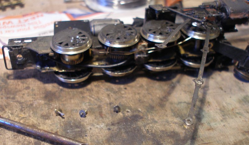
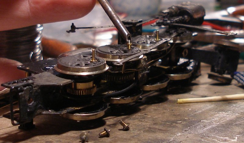
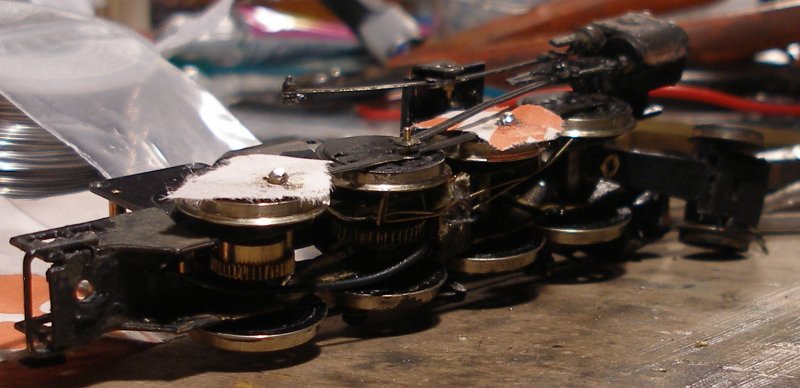
The photo below shows the loco back on the workbench with the motion stripped down on one side. A couple things date the original build. It can be seen that the wheels are actually spoked Romford's with etched overlays applied, and even more interesting, the crank pins screw in, but lack the grooves for the Romford wheel screw-driver to engage with. And getting them out has consequently required a pair of pliers. As this loco has now 'shed' a set of pins, the new pins will be fixed with a mere smear of Superglue - not ideal, but I don't want to have to strip the motion down again. There is no obvious reason (good clearances, easily turned by hand, no obvious pinch points) why the pins have unscrewed, so here's hoping that this is a one-off event! The loco with its motion taken down is shown below, with the 'blind' crank pins in the foreground.
Posted 6 March 2015
The Romford system of self-quatering wheels and screw-in crank pins is a great system, as it has stood the test of time, and ensures an accurate fit 'every time' without the need to adjust the quartering axles-by-axle as the 'true scale' systems do. Here's a blow-by-blow account of how the crank pins were upgraded on the WD.
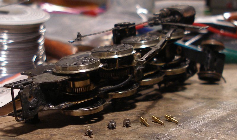
The new crank pins are laid out on the bench alongside the old set. As previously noted, the originals are 'blind' in that they don't have the cuts in the face to take the Romford screw driver. This would have meant that they would have been screwed in using a pair of pliers, which is probably why they have now worked loose.
The screw threads of the pins have a small smear of superglue applied and are then screwed in using the Romford screw driver. Note: this means that it won't be possible to replace the pins at a later date as they are now permanently fixed.
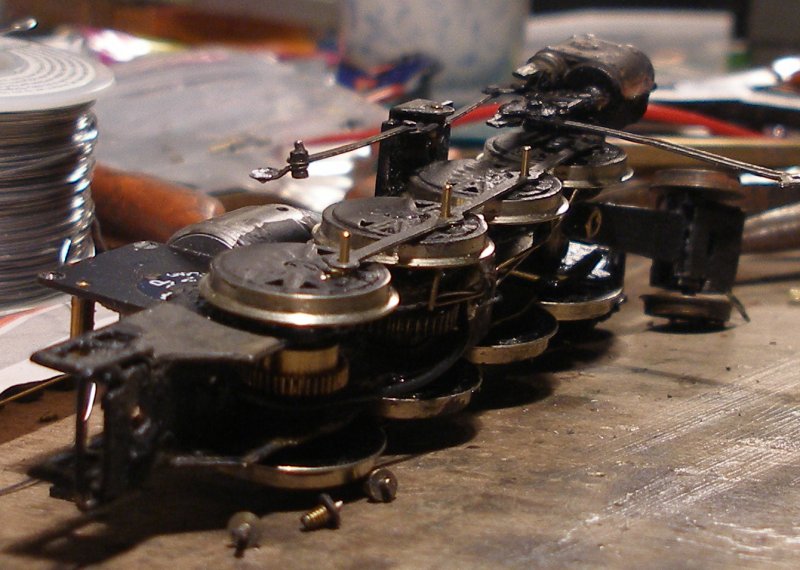
The three new pins have now been screwed in, and the coupling rod fitted back over the pins.
Small pieces of newspaper are pushed over the crank pins so that they lie on top of the coupling rod, and then the crank pin bushes are pushed onto the crank pins. A small blob of flux paste is then applied to the top of the crank pin and top surface of the bush. Note that the middle pin is left till later.
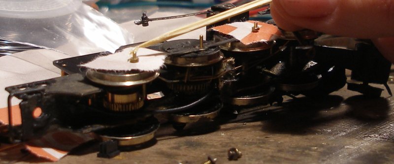
Now the soldering iron and solder is applied to the top of the crank pin bush.
The end of the pins are cut off, and the ends lightly dressed with a file. Don't file them to their final height at this stage, as they may yet have to removed and remounted, and it is best to have a little of 'play' available, particularly as these pins have been superglued in, and there's no way back! The connecting rod has now been fitted over the middle crank pin.
It is a good idea to add a crank pin bush before fitting the connecting rod so that the return crank does not hit the rods when rotating. The return crank is now soldered into place.
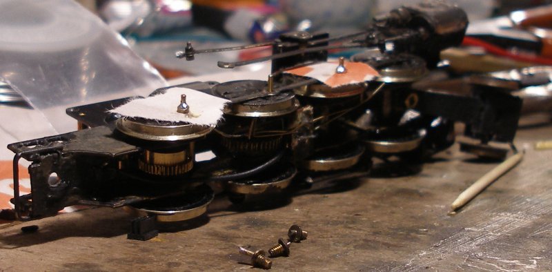
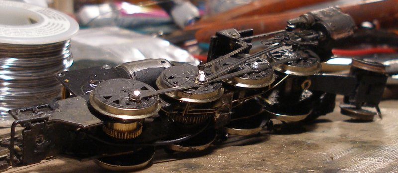
Fitting Romford crank pins -8: The rods are back on, the some shake down running is being performed. As can be seen, the crank pins have still to be thinned (filed) down and then painted.
The rods and wheels are a blur in this action shot, proving that they do indeed rotate. The loco is 'held' whilst the wheels are allowed to turn under power.
Posted 8 March 2015
Although the loco was now running, there was an erratic element - the sort of thing that you get with dirty wheels/track in DCC. Yet the wheels had been cleaned as part of the prepping. The loco was purchased off eBay about 10 years ago and left awaiting restoration. Examination of the driving wheel tyres suggested that they might have some pitting on the surfaces. Consultation of the 'forums' also yielded potential solutions, which gave us:
1. replace the driving wheels
2. fit a 'stay alive'
3. fit additional pick-ups on the tender
Replacing the driving wheels seemed a tad extreme, and there is both a time and cost penalty. Fitting a 'stay alive' would require soldering the wires onto the decoder, and there is again a cost penalty - current prices are around the £26 mark. The forums are divided on whether these work or not; some people have had locos totally rejuvenated, whilst others seem to have not seen any appreciable difference. For the 'stay alive' to work, the ability to run on DC has to be disabled and I don't like have 'exceptions' in the fleet, preferring to have everything work the same way. So that left extra pick-ups.
This is how it was done.
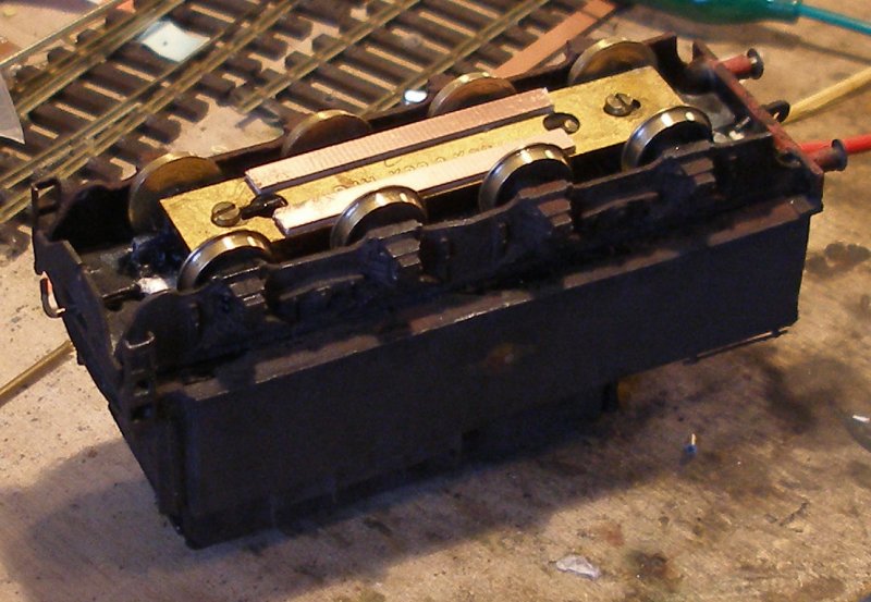
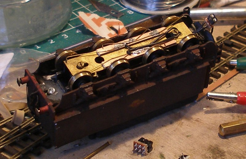
Two pieces of copper paxolin (sleeper strip) are superglued to the bottom of the tender keeper plate.
The first pick-up is formed from Alan Gibson handrail wire, and soldered to the copper paxolin. Note how this rubs on the first and fourth wheels.
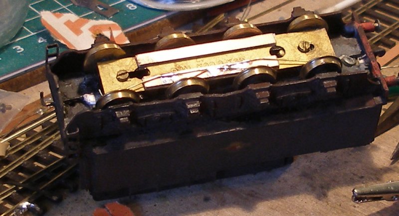
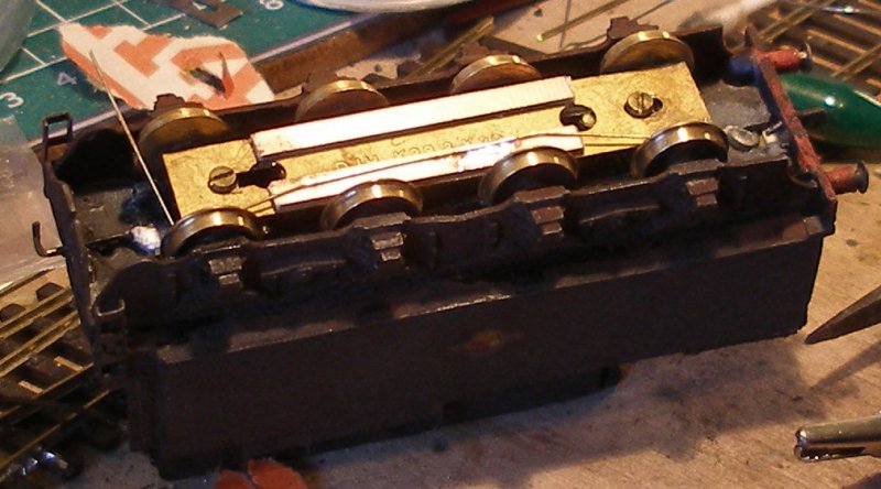
The second pick-up is formed and sits inside the first pick-up, bearing on the second and third wheels.
The process is now repeated on the other side so that there are now two sets of pick-ups bearing on all eight wheels.
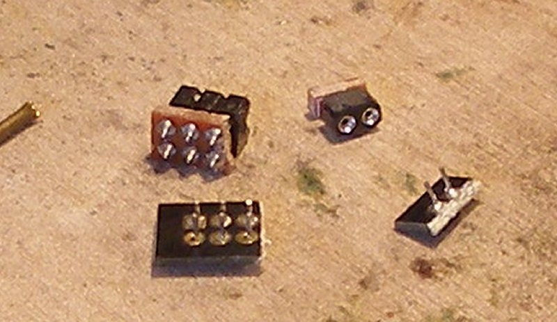
A pair of sockets is cut from a DCC socket, and the plug formed from two pins on a spare blanking plate. Bote that there is a piece of brass embedded in the service of the plate between the two pins which has to be cut through to ensure the two pins are electrically separate.
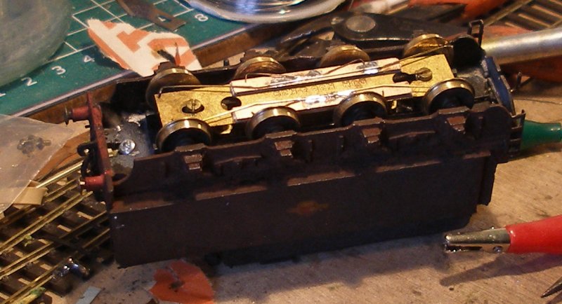
Two wires are soldered to the pins on the newly formed socket, and the wires are then fed back through the hole in the keeper plate and soldered to the two pieces of paxolin.
Two wires are soldered to the pins on the newly formed plug and then fed back through the chassis to the points where the locos own pick-ups are terminated.
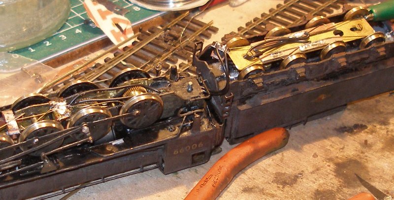
Finally, the loco and tender are coupled back together, and the plug and socket connected. Before leaving the work bench, the loco was checked for any shorts. This was where it was discovered there was a piece of copper connecting the two pins on the slice of blanking plug.
The loco now starts first time, and runs steadily, with none of the erratic stop-go running previously observed.
Posted 11 March 2015
<<< Workshop for a model railway layout Readying a DJH Crab >>>

Copyright J K Wallace, t/a 'Hall Royd Junction' 2013-2023 email: Hall Royd Junction
7 Portobello Close, Chesham, Bucks. HP5 2PL, UK
tel: +44 (0)7513 412880