
<<< Restoration of a DJH WD 2-8-0
New Comet Chassis for OO scale Black 5 44993
I acquired a rather nice looking 'repair or spares' kit-built Black 5 off eBay about 12 years ago. It was a nicely built and finished loco - that didn't work! I haven't been able to identify the manufacturer, except to say it is brass, and could even be scratch built.
The loco was numbered 44998, which according to my Ian Allan 1963 Locoshed book was allocated top Perth. I am not sure of the make of transfer, and opted to modify the existing number. The closest. most suitable loco was 44993 allocated to Carlisle Kingmoor. The photo below shows this simple 'mod'.
The chassis had the Romford Bulldog motor driving onto the centre axle, and with the front and rear axles in a sub-frame and sprung. Some initial tinkering, and the fitting of a Portescap RG4 motor and gear-box, dealt with the non-working motor problem, but there was clearly something wrong as the mechanism had 'a bag of nails' quality when it ran.
This thread tells the story of how a Comet chassis was constructed to take the re-usable parts from the original chassis to create a working entity.
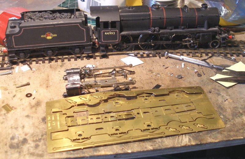
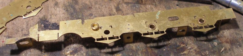
The Comet Black 5 chassis fret before the frames are removed. The body and tender have been temporarily placed on an earlier Comet chassis to test the fit, whilst the cylinder block and valve gear sub-assembly await fitting.
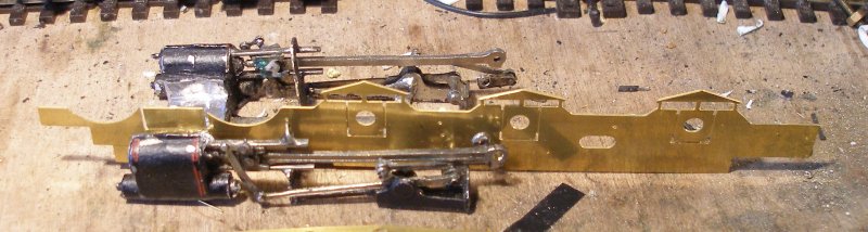
A frame member is offered up to the original cylinder block.
The chassis member was offered up to the body to determine the location of the spacers, and the spacers were then soldered into place.
The second frame member is offered up to check the fit.
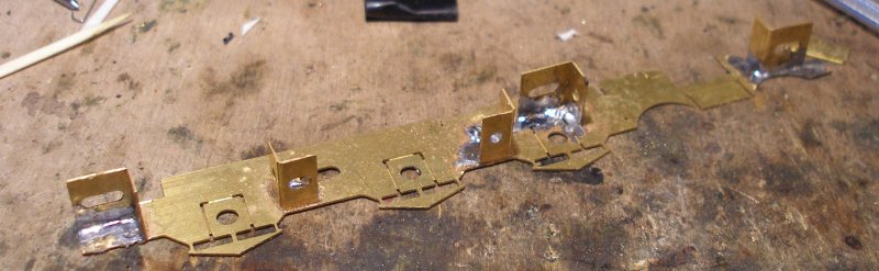
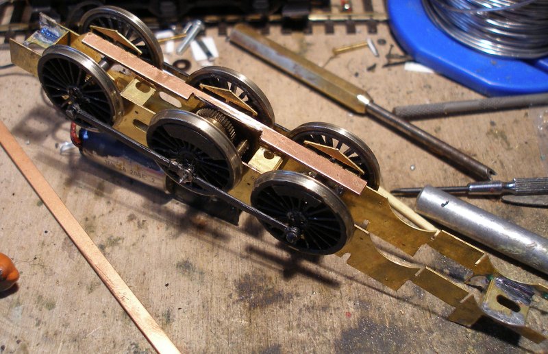
Bearings are required, and Romford standard 1/8th top hat bearings have been inserted into the axle holes.
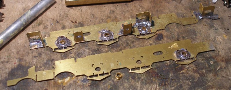
The top hat bearings are soldered into the frames.
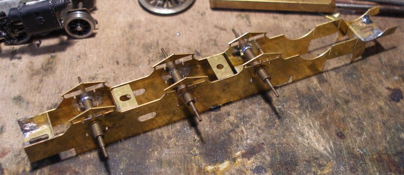
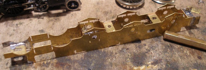
The axle alignment is tested using an axle set designed for aligning sprung axle boxes.
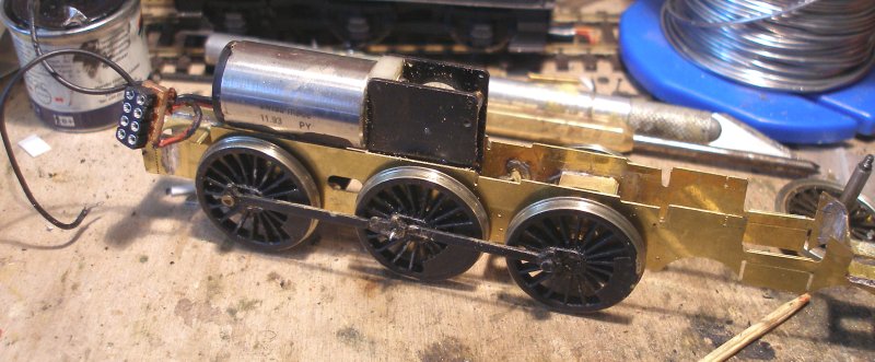
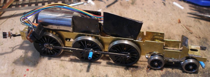
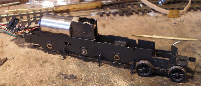
With the chassis assembly the Portescap RG4, leads, Romford wheels and coupling rods from the donor chassis were quickly fitted to the new chassis.
Copper paxolin was glued to the two spacers placed to support the pick-ups.
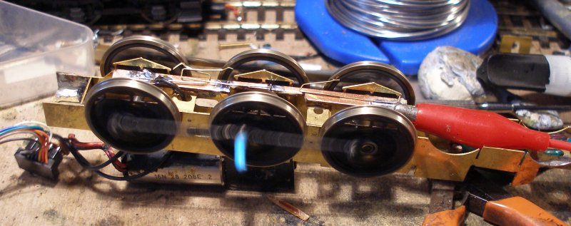
Pick-ups have been formed from Alan Gibson 0.33 mm handrail wire. Power has been applied and the wheels are spinning.
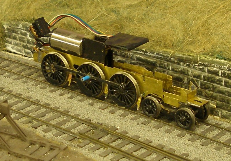
The first self-propelled test run.
As the original tender pick-up connection has been imported with the motor, a second run was made to check that the pick-ups were correctly orientated.
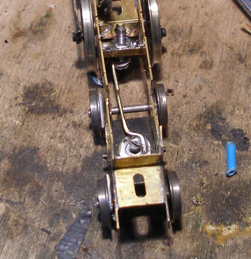
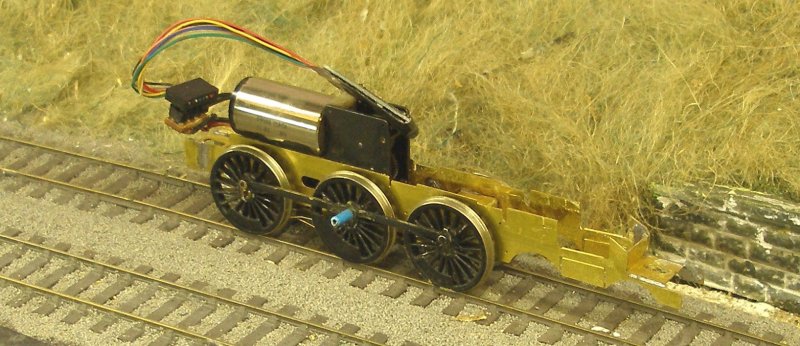
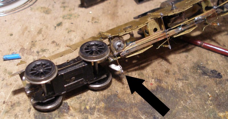
Now the bogie could be refitted. A nut was soldered into the stretcher and a bolt inserted from below to secure the bogie.
A second view of the bogie now in place.
Another test run on the layout to check bogie clearances. There were problems with clearances with the front of the frame coming into contact with the front bogie wheel, and as there was little metal to play with, this was cut off, to be replaced in plastic.
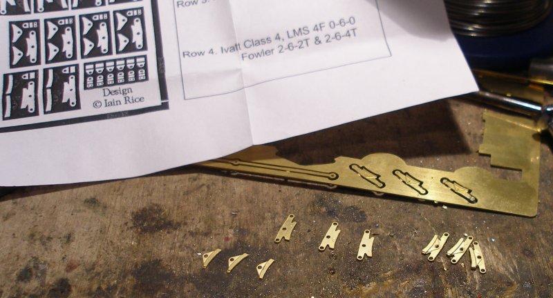
The LMS Mainly Trains brake gear fret was examined, but the blocks were larger than the Comet Black 5 set and so were rejected for this model.
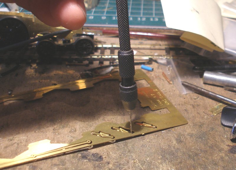
The brake blocks on the Comet fret were now drilled top and bottom to take the brake gear rodding.
The rodding is inserted through the holes in the frames and the blocks soldered in place.
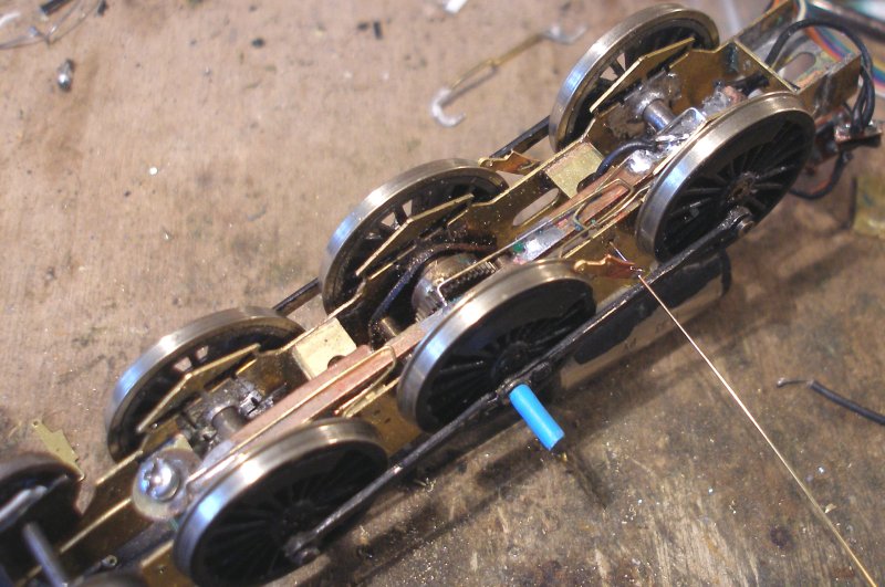
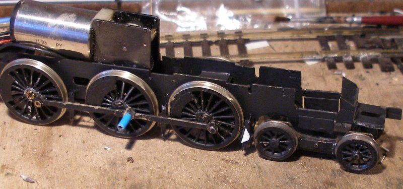
The brake gear is now fully assembled.
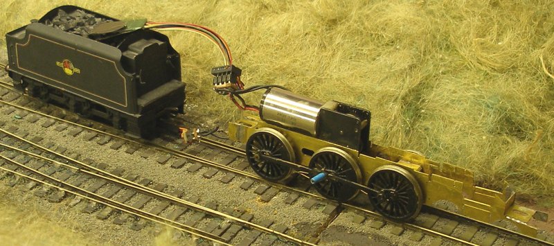
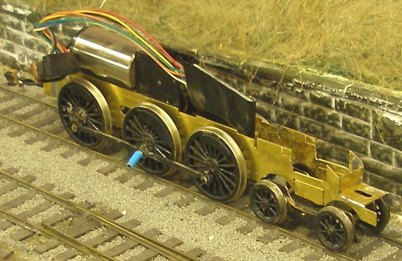
A third test run with bogie and brake gear in place. Although there appears to be sufficient space between the rear bogie wheel and the front brake block, there was a wonderful display of sparks on the 3-foot radius balloon loop. This wasn't sufficient to trip the short circuit detection, but provided a continuous display as the loco traversed the loop. The wheel continued to rotate so...
A plastic shim was glued to the inside of the offending brake block, which was marginally proud of the metal fitting.
Wheels removed to allow the frames to be painted.
There was still some marginal contact between the bogie wheel and the front brake block, so a block was fashioned from plasticard and fitted to the front of the rigging, again overlapping the metal brake gear. A small fillet of Araldite was added to the front of the assembly to ensure that there could be no metal-to-metal contact.
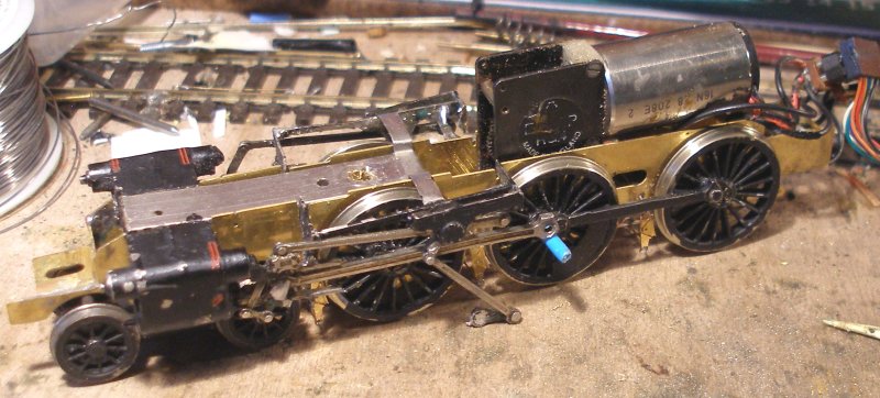
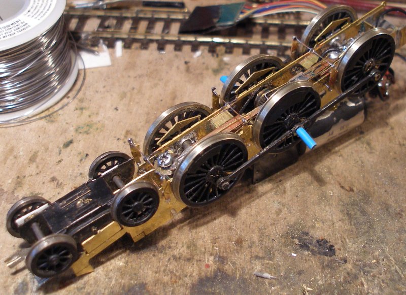
Finally, the valve gear and cylinder sub-assembly are trial fitted.
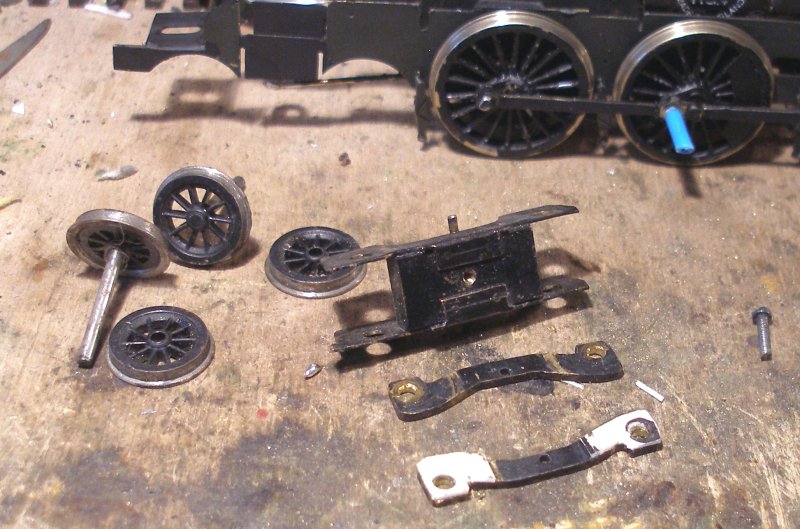
The original front bogie was now dismantled, cleaned and painted. This is a nicely engineered item with compensated side bearers.
Construction to this point has taken 7 hours.
Posted 21 June 2015
<<< Restoration of a DJH WD 2-8-0
Copyright J K Wallace, t/a 'Hall Royd Junction' 2013-2023 email: Hall Royd Junction
7 Portobello Close, Chesham, Bucks. HP5 2PL, UK
tel: +44 (0)7513 412880