
NCE Power Cab v the Lenz compact
Installation | Power Supply | Difficult Locos | Enhancements | Accessory Decoders
This page records my NCE Powercab journey, starting with first experiences at the bottom of this page.
Partial relief - booster installation (28 February 2018)
The flaw with the plan to use the Tam Valley DAB002 Booster Board and the TRDAB16 16 volt Booster Power Supply was that Digitrains were out of stock. Enquiries to other UK stockists drew a blank, so it was a case of hunkering down and awaiting fresh supplies.
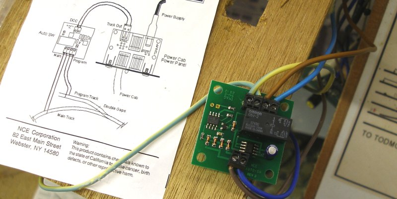
The photo illustrates what was ordered.
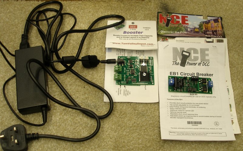
Interestingly both the EB1 Circuit Breaker and the Booster have jumpers, and which have to be configured. The booster allows differing amperages to be selected, and trial and error established that 5 amps was too low, but that 6 amps was just right. The instructions suggest testing that the cut out works using a coin to short the two rails.
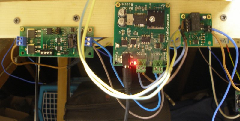
In my set-up there is programming track module, so the programming track module is wired directly to the booster. The booster is wired to the circuit breaker, which in turn is wired to the track feed.
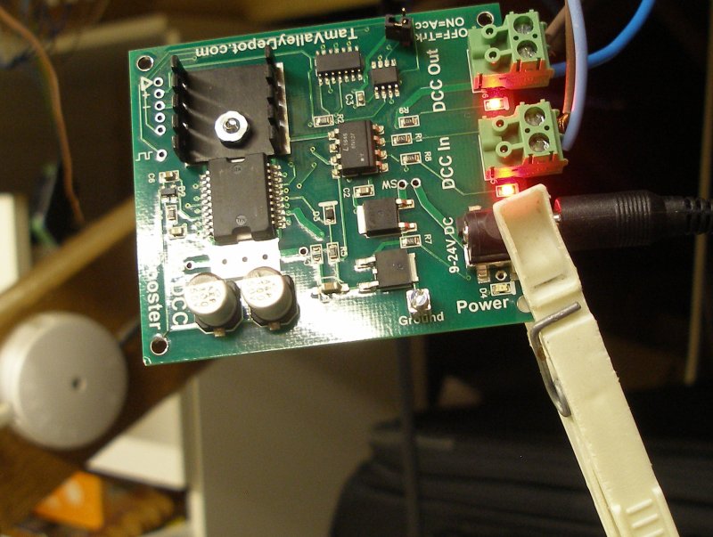
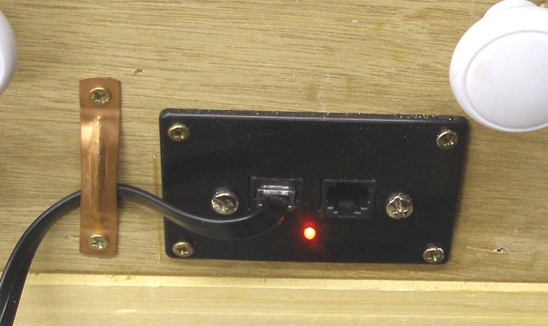
However, when the power supply was plugged into the booster, the socket did not seem to be rigidly fixed to the board, and when power was applied only one LED was illuminated, as shown in the photo below.
When the socket was pressed against the board, both LEDs lit, and the circuit breaker was active. It was possible to clamp the socket to the board with a clothes peg, which allowed the board to function correctly.
Ringing Digitrains on the first day of the 'Beast from the East' snow storm suggested that they had prudently gone home early. Arranging a replacement will therefore have to wait for another day.
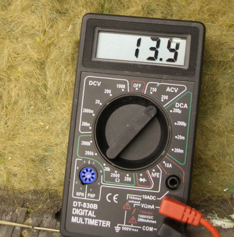
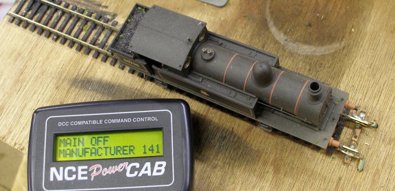
However, with the new boards functioning, it was possible to test the track power to see if there was any improvement on the 11.6 volts previously recorded. It had been established that the Powercab was providing 14.8 volts with the layout disconnected. As the photo below shows, the 13.9 volts now being obtained represents a significant improvement. The next question is whether a second booster - with the layout slit into two power districts - would see a further improvement. This will require some further testing, and will also be dependent on further stocks of Tam Valley booster arriving in the UK.
One final note. I have found that the small jumpers that are stored on the boards in the passive position have a tendency to fall off. The spare ones were placed in the bag that the screws came in, and then stapled to the back of the instruction sheet, and placed in the plastic leaflet holder screwed to the front of the layout to hold the DCC literature.
Go slow imposed by layout (28 January 2018)
It was becoming increasingly apparent that certain locos were running - once more - more slowly to the point that running was too slow. Anyone who has read through these notes will realize this seems to be a recurring theme; locos run slow, low voltage is suspected. The power supply is upgrade and locos run better.
The fleet of Calder Valley Jubilees has slowly being growing: 'Mars' representing Bank Hall in Liverpool, together with a collection of Leeds-based locos for the summer weekend Blackpools.
As the layout slowly evolves, the setting-up of specific trains and motive power for tem has started. 'Mars' heads the 9-car 10.05 Liverpool Exchange - Newcastle, whilst the others have various 'scratch' excursion rakes, also running to 8 or 9 cars.
To say that having finally got round to creating correct train formations, to say I was disappointed with the performance is putting it mildly. The conundrum was that a fair bit of time had been expended playing with different power options until everything was running well, and then to find that running had deteriorated again was surprising.
The Hall Royd Jubilees are a wonderful mixed bag. They represent a cross-section of British modelling - two use the Hornby Scot chassis; two have the modern Bachmann (not split chassis) type; two have brass chassis' with Portescap RG4s; and one has with a Mashima and High Level 30-1 gear box.
The Portescap and Hornby locos were running well with a 9-car load, although with a top speed of maybe 60 scale miles per hour. But the Bachmann and Mashima locos were running at around the 20 mph mark - hopelessly slow for what are supposed to be express trains.
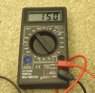
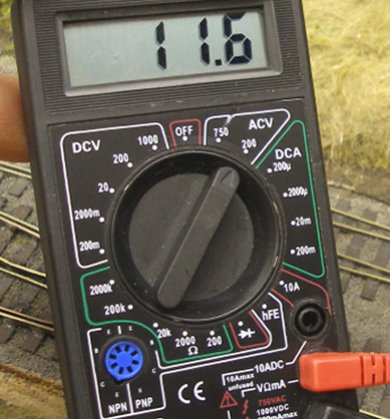
Investigation with a multimeter quickly identified the problem. The input voltage from the Digitrains 13 amp power adapter was 15 volts, but at the track only 11.6 volts. Worse, at the top end of the layout (where there was a falling off of performance) the track voltage was to 11.1 volts. This latter problem was relatively easy to fix with extra power leads added across the baseboard joint.
Note that to measure the output from the transformer, the DCV-200 setting is used, whereas to measure the track voltage ACV-200 has been selected. This, by the way, is how the US-based 'Model Railroader' suggests it should be done.
In the interests of balance, I share here a comment posted by Dave Heap on the Yahoo! NCE group: "You can't compare VDC readings with VAC readings using an ordinary DMM unless your VAC is a 50-60Hz sine wave, which a DCC signal is not. Your meter could read either higher or lower on the DCC side, either is likely, depending on the AC frequency response of the DMM (a meter designed only for 50-60Hz voltage measurement is likely to read too low, a meter designed for audio frequency voltage measurement is likely to read too high)." You've been warned :-)
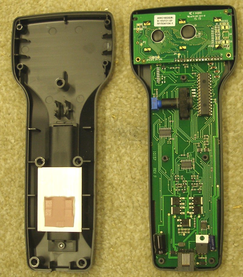
Taking the back of the NCE Powercab didn't reveal anything obviously amiss.
It was also established that the programming track module took about 0.4 volts. There was also an impedance problem at one end of the layout where voltage dropped to 11.1 volts. The wiring was adjusted, which eliminated this issue.
First thoughts were that there was a problem either with the socket that the Powercab and power supply plug into; with the flat backed cable or with the throttle. The consensus on the various groups was that it probably wasn't the throttle.although the cable was viewed with some suspicion.
I finally rang Jeremy at Digitrains. He suggested disconnecting the layout and taking a reading of the output.
Without the layout connected, I was getting 15 volts in and 14.8 volts out.
Jeremy's conclusion was that a booster was needed, and that the Tam Valley unit would probably meet my part particular needs. For the record, the booster board is the DAB002 and the power supply is reference TRDAB16. He also strongly recommended the EB1 circuit breaker, on the basis that the power available via the booster would be capable of melting loco bodies if unchecked.
Further updates when the gear arrives.
28 January 2018
Programming Accessory Decoders with the NCE Powercab (11 November 2016)
There are two half pages (31 & 59) is devoted to programming Accessory Decoders in the NCE Powercab manual. This maybe because it is easy to do, and after struggling with loco decoders, most modellers find this a breeze.
What is missing from the NCE documentation (both in the manual, and on their Website) is an overview of the process. What follows may therefore seem obvious to many users, but I am going to share what I learned as I learnt it.
Loco decoders can be programmed either on the 'Main' or on the 'Programming Track'. So here's the first difference, Accessory Decoders can only be programmed on the 'Main'. If you think about it, the Accessory Decoder is a fixed part of the layout infrastructure, and so is difficult to programme the individual units prior to their installation.
So in the same way that a loco on the 'Main' has to identify itself to the Powercab throttle, so does the Accessory Decoder.
Each decoder manufacturer has approached the problem of programming their piece of kit differently, although there are some re-occuring themes. Likewise, the throttle manufacturers are going to be a tad vague in their manuals as they can't test every piece of kit out there, and so have to provide a set of 'universal' instructions.
Manufacturers have adopted two approaches. The first is proper programming, and the second is termed 'learning'.
The first is akin to how you might code a loco decoder, with values written to a series of CVs. This process is described on page 31. Press the 'Esc' button (bottom left hand corner of throttle) and press it seven times until the message 'XXXXXXXXXXXXX' appears, and then press enter. The display will now invite you to enter the CV number and the value to be written to it.
Turning to Page 59 of the Powercab manual, this what it says:
PROGRAM ACCESSORY DECODERS
This allows the operator to set Accessory Decoder CVs while they are connected to the Track (Accessory Programming on the Main).
ENTER THE ACCESSORY ADDRESS
Enter the Accessory Decoder address and press ENTER
ENTER THE CV NUMBER
Enter the CV number that you want to program and press ENTER
ENTER THE CV VALUE
Enter the CV value that you want to program and press ENTER
This does not appear to apply to the 'self-learning' type of decoder, and so unless the decoder manufacturer's instructions specifically require individual CVs to be decoded, can be ignored.
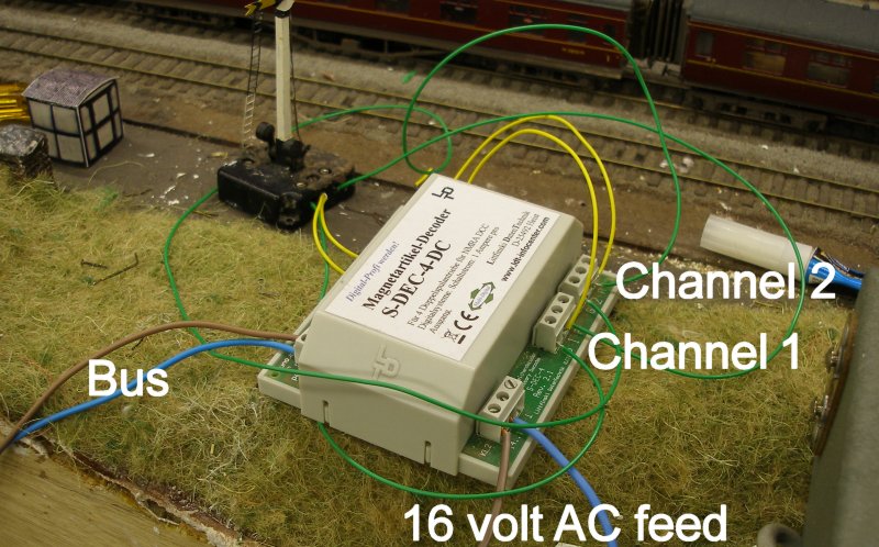
Programming the Littfinski Daten Technik (LDT) S-DEC-4-DC-G
In my initial phase, I bought two 4-port accessory decoders. These were the LDT S-DEC-4-DC-G type, and can be bought ready-made or in kit-form from Digitrains. The instructions can be found here.
It is worth noting that this will only handle accessories up to 1 Amp, so technically are not suitable for any of the PECO-type solenoids, including the 'DCC' (green) one, which draws over an Amp. I found that, as per the instructions, it worked best when an independent power supply was used to drive the accessories. I have an old H&M controller with a suitable
The manual is not the best. However it appears that the LDT accessory decoders are “self-programming/learning" using the "S1" button on the decoder board. Here's what you need to do:
1. Press the 'S1' button on the Littfinski Daten Technik (LDT) S-DEC-4-DC-G board to start the programming process.
2. The signal arms start to move up and down (as stated in the manual).
3. Using the Powercab, select Accessory 1**, and then on the next screen selected '1' for ON, and press ENTER.
4. The signal arms wags even faster, indicating that the programming process is complete.
5. Press 'S1' again to end the programming process, and the arms stop waving up and down.
6. Selected Accessory 1 on the throttle, and then '1' to switch the signal.
I will now share a silly mistake in the hope that others won't fall into the same trap.
Having got the LDT to work as Accessory 1, I wanted to promote it, and therefore set about giving it a new address. I had already realised that 4-port blocks or similar work best when the four addresses are in sequence. So if Accessory 1 is the first one, then the other three will be 2,3 and 4. Without thinking too much about this, I decided to make the first Port Accessory 20, on the basis that 4 neatly divides into 20, and that therefore the first Accessory should be #20. The signal responded correctly as it was being programmmed, but did not work when Accessory 20 was selected.
I am deeply grateful to Joff Hamilton on the NCE-DCC Yahoo! group who gently pointed out the error in my basic maths. If the decoder has 4 ports, and assuming that it is programmed to make the first port the first number in a group of 4, then the first numbers that can be used are 1, 5, 9, 13, 17, 21, etc. Joff noted that LDT decoders are set out in blocks of four, starting at 1. So, 20 will not work, but 21 should! Joff believes this fact is buried somewhere deep on the LDT Website.
Joff has also set about programming an LS-DEC-BR using the NCE Powercab for 4-aspect colour light signals:
Joff writes: "I have just completed the programming of the LDT LS-DEC-BR.
In short, if you have 4 signals, starting at 1, they will be numbered 1,3,5 and 7. To program, put the jumper on J3, press the 'S1' key, Select Accy 1, press 'Enter' and press 1. The two left hand side lights will flash. Press 'S1' again and Select Accy 5. Press 1 and the right hand lights will flash. Press 'S1' again and the lights will revert to red. Remove the J3.
Then, depending on the number of aspects, for 2 aspect simply select the accessory number 1, for example. Pressing 1 should give green – 2 gives red.
For a 4 aspect signal, to get to single or double yellow, simply select the accessory 1 higher, so for signal 1, select accessory 2 and toggle 1 & 2."
Cobalt ADS-2fx
The Cobalt is a delight to use, and unlike the other two decoders reviewed here, tells you everything you need to know in the instruction sheet!
DCC Concepts claim that they have designed their model railway equipment with ease-of-use in mind, and this certainly seems to be the case.
The problem with switching solenoids of all shapes and sizes is they require quite a lot of power, which is usually not available in the layout bus. This means that a separate power supply is required, and so the much vaunted DCC benefit of 'only two wires' immediately becomes four wires. DCC Concepts have got round this problem by fitted a capacitor on each channel, so that there is enough umph to throw the signal or point.
The steps to install the decoder are:
1. connect the unit to the track bus or dcc accessory bus using the two terminals at the end of the longer green terminal strip (marked on the board)
2. Decide on the Accessory number that the two channels are to have - there is no restriction.
3. Carefully move the set/run switch on the channel being programmed to the 'set' position - so it moves towards the edge of the board.
4. Now take the NCE throttle and press the Accessory button, and then tap in the chosen number - just the number without any zeros - and press enter. On the next screen select '1' for ON, and press 'enter'. There will NOT be any movement of the accessory, as some flash or flicker to indicate the programming is complete.
5. Finally, reverse the 'set'run' switch back to the 'RUN' position. You are done!
Minx DC adaptor
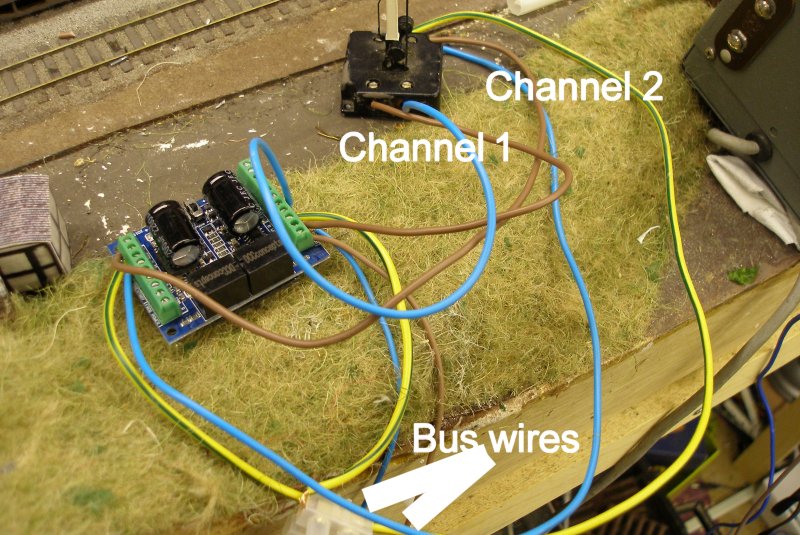
The standard Minx command unit controls two devices (so 2 points switched either way). In the installation below there are two command units intended to drive 4 points. This wont win any wiring competitions, but is still very much in the 'first fix' stage as the various wiring options are tested and assessed. In this version, there is still a set of connections to on/off switches on the soon-to-be-retired control panel for remote operation.

The DCC modules have been inserted into the socket on the top of the unit. The full instructions are here.
Each control unit has two channels and only one programming button. The programming button is pressed, and the Accessory selected on the the NCE throttle. As previously noted for the LDT decoder, this must be a number in the range 1, 5, 9, 13, 17, 21, etc. The second channel will self programme with the next number in the sequence, so if Channel 1 is '5', then the second channel will be '6'.
Now I have two of these units, and the rule of 4 applies to this as well. So if Channel 1 on Unit 1 is '5', then Channel 1 on Unit 2 should be '9', and the second channel on Unit 2 will automatically be assigned '10'.
Having programmed one unit, I turned to the second, and went through the programming sequence. It appeared that the adjacent unit had reprogrammed itself using the newly applied accessory code. The solution seemed to be programme unit 1with unit 2 disconnected from the bus, and then reverse the process with unit 2 connected, and unit 1 disconnected. Finally, reconnect both units to the bus.
It was possible to programme other accessory decoders with the missing numbers - in this case 7 and 8.
However, to make like easier and to ensure that the Minx units have a clear block of numbers, I have reprogrammed them as 101 and 105.
Conclusion
From a DCC perspective, of the three types of Accessory Decoder assessed, the DCC Concepts Cobalt ADS-2fx is the superior unit (and now upgraded).
Critically, it does not need an independent power supply (the Minx needs a clean 12 volt supply, and the LDT a 16 volt AC one), so wiring is greatly simplified.
The programming is easier, in that each channel is coded separately so allowing each Accessory to have a unique number, rather than being one in a set series.
And delightfully, the instructions tell you everything you need to know to complete the process. I would not have resolved the numbering issues with the LDT if I had not had access to the NCE-DCC group, and critically, there was no hint in the instructions about the importance of choosing a particular number, or how this would then be replayed to the other channels.
The Minx was much better in this respect, although its instructions failed to mention how Channel 2 would be assigned its number, or how a second unit might be programmed. However, having 'cracked' the LDT coding, it became obvious how the Minx was working. However, the Minx introduced greater complexity into the layout, and has now been removed.
Some of the points will be required to be worked together, and the 'Use of Macros to Control Turnouts' (page33 in the Powercab manual) will be the subject of a further post.
11 November 2016
10 Month Review (2 November 2016)
These notes are written some 10 months after the NCE Powercab was first deployed.
The NCE Powercab remains a remarkably straight forward system to use, with a 'comfortabe' throttle.
There was a small group of hand-assembled locos - generally with Mashimas with high-ratio gearboxes (geared for slow running) - which ran more slowly than they had with the Lenz compact. These have now been re-boxed with High-Level gear boxes using the lower ratios available, and have now 'disappeared' in that they now run as well as the rest of the fleet and no longer stand out as poor performers.
In the original installation I opted for a Double Pole Double Throw (DPDT) switch to select the Programming Track. This was mounted next to the track, but the inevitable happened and I did start the process of re-programming the entire loco stud. This might be described as a weakness, but on the other hand the Powercab is offered as a basic starter system, and it is up to the user to determine the additional facilities required, and the level of budget. Personally I like the way the NCE system can be gradually upgraded and enhanced both as funding permits and as the user gains knowledge of what is right for their particular set-up.
Consequently I have now bought a Auto SW unit for £16.63 (Post-Brexit but before higher prices start to be passed on). This replaces the DPDT switch (the connections are identical) but crucially it automatically routes power to the programming track when 'Programming Track' is selected on the throttle.
I also wanted the flexibility to operate the engineering sidings which are some distance from the control panel. Although there is a fair amount of cable attached to the throttle, the yard was still beyond a comfortable operating distance. Again, NCE have made it very easy to extend the Powercab system and has enabled the provision of additional sockets to plug throttles in at multiple locations.
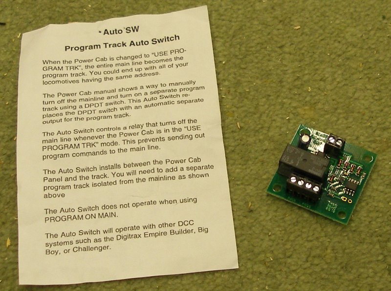
NEC Auto SW module as delivered
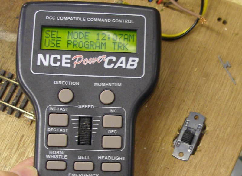
The DPDT switch in use, with 'Use Program Track' selected on the Powercab throttle.
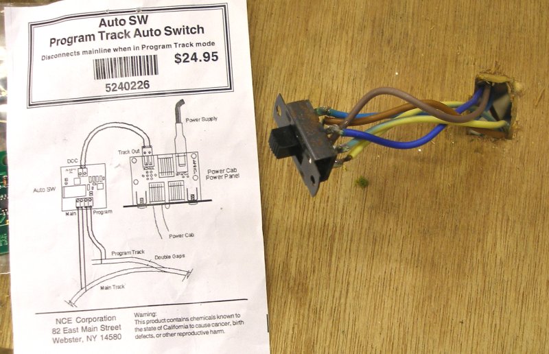
The DPDT switch was gently removed from the programming track bench to allow access to the wires at the back.
It literally is the work of minutes to cut off the wires from the switch, bare the ends and affix in the screw sockets provided.
The NEC Auto SW module has performed as advertised. Immediately Programming Track was selected, the throttle has switched off the Main and is rooting the output to the Programming Track.
To facilitate plugging in the throttles at convenient points around the layout, a U.T.P fascia plate for NCE is required costing £15.83 (again, just after Brexit), together with a cable. This is a RJ12-3 CAB BUS CABLE (3 METRES) from Digitrains. NCE note in the instructions that the cable is wired in parallel, so a phone cable with similar jacks is not suitable. Do make sure you order the cable at the same time, as the spare flexi-cable provided with the original Powercab is for when the Powercab is used as a separate throttle in a PowerPro set-up.
It is worth pointing out that the various vendor Websites do not always flag up the need for the additional cabling.
Also note that the master throttle (the T-shaped) one must always be plugged into the main socket (the left hand socket), and that only the smaller hand held throttles can be plugged into the additional UTP sockets dotted round the fascia.
The UTP panel is mounted at the desired location. The RJ12-3 CAB BUS CABLE is then plugged into the back of the UTP plate, with the other end plugged into the back of the original panel. This is a continuous cable which I have simply hung under the baseboards, and is not routed through the regular inter-baseboard connections. It would therefore have to be unplugged if baseboards were being removed. The UTP plate has two sockets both front and rear. The second rear socket allows a further run to feed additional UTP plates, whilst the front sockets allow two hand held throttles to be plugged in.
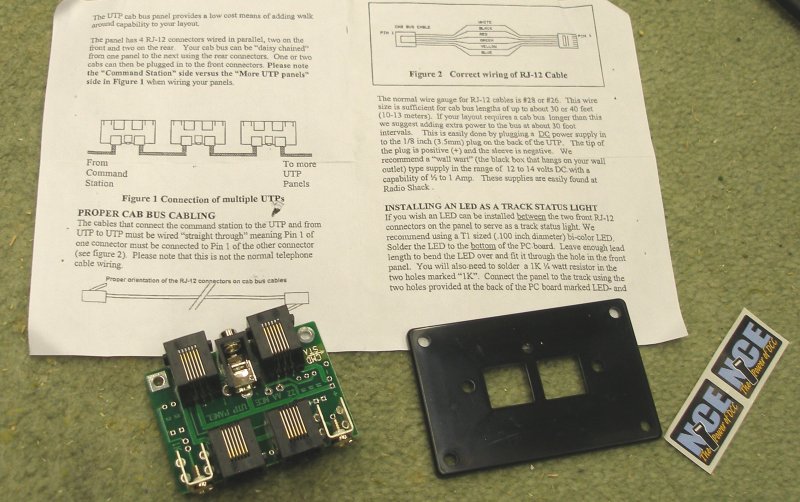
Clear instructions are provided with the NEC UTP module - but no wire!!
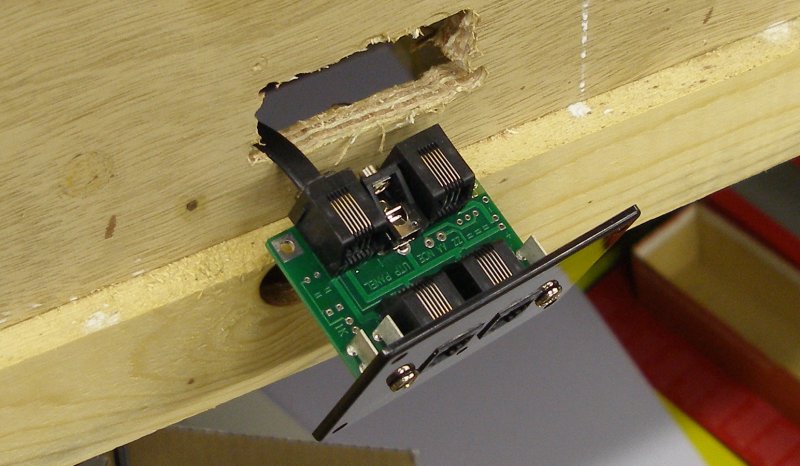
Installation of the NEC UTP is very quick and simple. A hole is cut in the panel. The RJ12 is plugged into one of the rear sockets and the wire fed through the hole.
The RJ12 cable is fed along the underside of the baseboard, and plugged into the socket in the middle of the original NCE Powercab socket. The throttle is then plugged in and you are literally ready to go!
This extension was a great success, as it created a second operating position easily and quickly. The NCE system allows multiple such extensions, and I subsequently added a second extension providing a plug-in point at the far end of the layout. This now means I can plug in the Cab06 at three separate locations, which has made for a greatly superior layout operating experience.
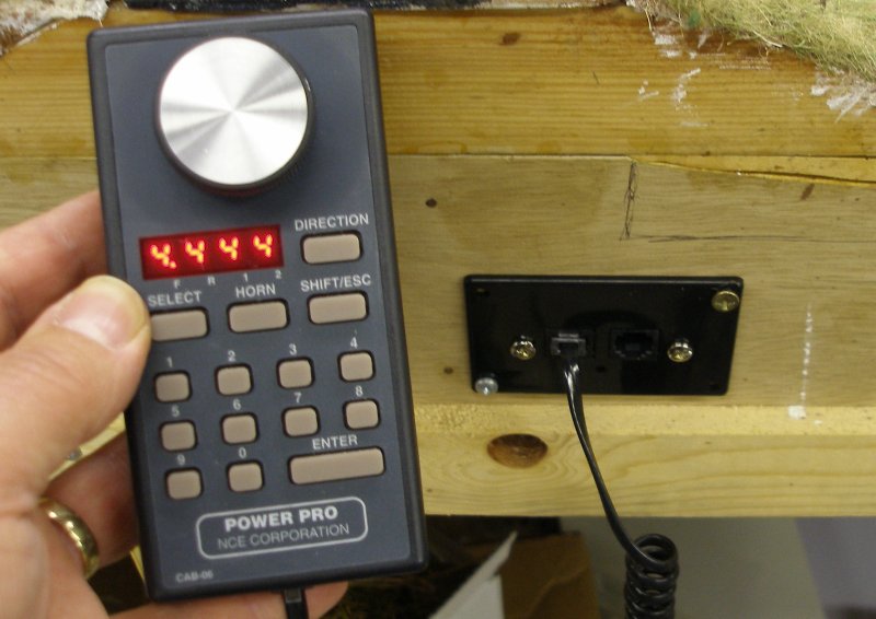
Correspondence with chums, and also brought up on the NCE Yahoo! group is the vunerability of the plug for the flat throttle cable. The image below shows my simple solution:
2 November 2016
Programming mystery resolved (19 January 2016)
The problem of three kit built locos running slowly remains unresolved, and various posts and pleas to the dedicated Web forums have been unanswered. And then this week a discussion on speed-steps suddenly struck a chord. I am reproducing Wouter van Doorn from the NCE-DCC Yahoo! group in full:
An additional complication arises when the programming system is not the system trains actually run on. Say, a Power Cab for programming and a PH-Pro as layout system. The Power Cab, in most cases, will not have the exact same track voltage as the PH-Pro (the Power Cab is, indeed, rather lacking in the voltage department, hurting large-scale operation). Different decoders can react differently to this:
1) they can chop up the available voltage in 28 steps;
2) they can have the responses to all the steps identical independent of the different track voltages BUT simply flatline when more higher) steps are available for which the voltage is insufficient.
I know my Massoth decoders follow policy 2), and they would never be able to work consistently with policy 1) decoders over systems with different voltages.
It confused the heck out of me until I realised what was going on.
Could this be what I am observing? Because I have just changed systems - from the 15 volt Lenz to - initially - the 12 volt NCE Powercab - it follows that all motive power units have been programmed either on the Lenz or on the Sprog plugged into the Laptop. However, nothing has yet been programmed using the Powrercab. The reason is that the Powercab needs a dedicated programming track selected using a DPDT switch, and this had been accorded a lower priority. Clearly, this is the next thing to try out.
19 January 2016
Jim Betz on the NCE-DCC Yahoo! group provided the following in a subsequent post:
"You say you have some older locos with older decoders that are "painfully slow". Although this seems like a 'big deal' - it is actually pretty easy.
Replace the decoders with current design, reprogram with your PowerCab. You will be happy you did - and the work is fairly easy (even if the original install was hard wired) and goes quickly.
I recommend you get a 2nd Power Cab Panel (PCP) and set up a permanent - totally isolated from the layout - programming track. This will give you excellent flexibility and will make all of your programming work easy.
I also strongly recommend setting up DecoderPro - which will require an NCE "USB interface" if you don't have one. Learning to use DecoderPro is easy - if you have someone who is a "guide" who will sit with you (while you do) during your first programming session. I'm sure you can find someone local to you who will help with that - if you live in the SF Bay Area contact me off list to set up a session.
To use DP you will also need to connect up a computer - it can be a laptop you use for other stuff or it can be a "layout computer". If this will be a computer that is being "re-purposed" for layout use it will be considerably simpler if it is a "Win 7 or better" computer. (There is a similar statement for Apple products but I don't know which IOS version is "the recommended minimum".)
Caveat - if those older locos still don't run correctly (fast enough) after doing the above ... then you may need to remotor them. But that is unlikely ... if they ran fast enough on DC they should also run fast enough on DCC.
For HO track it is recommended that the DCC track voltage be "around 14 volts" ... which is what the PowerCab will/should be providing ... and volts are -directly- related to how fast or slow your trains will run (or are capable of running).
Tonight's session was spent setting up a dedicated programming track. In my set-up, the programming track was located on a shelf close to the throttles. A DPDT switch was set in the surface of the shelf, and the two wires from the programming track soldered to the two terminals on the switch that are furthest from the layout. The two wires from the layout were then soldered to the two terminals closest to the layout. Finally the two wires from the back of the Powercab socket were soldered to the centre terminals, and the switch inserted into the hole previously cut in the programming track shelf.
When the switch is pushed towards the layout, the throttle is connected to the track. When it is pulled away from the layout, the programming track is live.
Finally, one of the 'affected' locos was placed on the programming track, and a number of CVs modified. The loco was placed back on the track, and 'top speed' was improved, although top speed was still not as fast as was achieved with DC.
Tomorrow I will look at the speed step settings, top speed and CV29 using the Powercab.
20:40 hrs 19 January 2016
Christmas over, and there's been time to start playing with the new toys.
Short Circuits
Short circuits are a curse on a DCC layout, and the NCE Powercab has a faster cut-out than the Lenz compact it was replacing.
This meant that the Gaugemaster relay-based reversing loop modules were too slow for the NCE, and had to be replaced. The advice from my two regular retailers was to upgrade with AR-1s, although contributors to the NCE Yahoo! group were recommending PSX-ARs. The AR-1s are adjustable, and it took a little while to set up the first one, whereas the second worked without adjustment.
I was having some difficulties when shorts arose with the Lenz compact: either random locos were reset to '3' or worse, chips would blow. So far the faster cut-out seems to have reduced or eliminated this problem, as since the NCE Powercab was installed, there have been no further instances of chips resetting to '3'.
However, if there is an irritation, it relates to the recovery position that the Powercab throttle adopts when it recovers from a short. The Lenz compact cut-out, and then had to be manually reset once the short circuit had been cleared. On resetting, the throttle would return to the selected settings (selected loco, direction and speed) at the time of the short.
By comparison, the Powercab the cut-out resets every 4 seconds until the short is cleared. However, on removal of the short, the throttle retains the selected loco but resets the speed (zero) and direction (forward). However, the layout of the Powercab throttle means it is easy to dial-up the previous settings.
Consisting
The various discussion groups all consistently make reference to how easy it is to set up 'consists'. This is when two or more locos are required to run together. In the British scheme of things, this is double heading, banking or when a Multiple Units run in multiple.
The Powercab consist area is marked on the throttle and has four buttons. The process is clearly detailed in the handbook, and it is easy to set-up and break-up 'consists'.
There are two types of 'consist' - Advanced and Old. I had installed the same chip throughout my Hornby/Lima DMU fleet, and I found it very easy to create a 6-car and 9-car consists using the Advanced configuration. However the Bachmann Class 108 (factory chipped) simply wouldn't play ball with the others.
I then attempted to double head using a Hornby Black 5 and 8F chipped using Lenz decoders. These wouldn't accept the 'Advanced' configuration. A fresh attempt using the 'Old' configuration, and immediate success.
It has to be said that 'consisting' is one of the most enjoyable aspects of DCC, and the Powercab facilitates this very well indeed.
More power... (23 December 2015)
Having now carried out extensive running of a variety of locomotives and train weights, there is a marked improvement in running across the board. However there remained three locomotives that were running poorly compared to how they run using the Lenz compact with its 15 volt output. The dilemma was to whether to focus on the matching the Lenz power supply or whether to see if the individual locomotives could be improved.
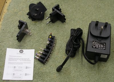
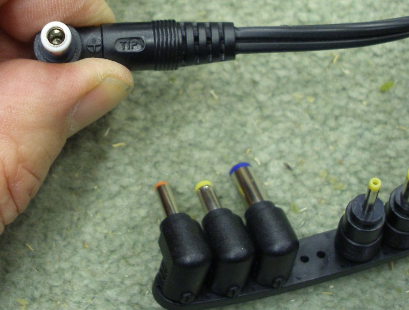
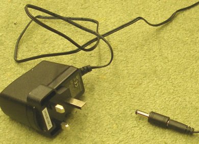
Digitrains offers a power adaptor with a 15 volt output which is not official NCE issue but is advertised as being compatible for a very reasonable £21.82. Having ordered one in mid-December 2015 I have to report that the Website is now showing it as 'Out of Stock'. On opening the box there is a power adaptor with a UK 13-amp 3-pin plug, together with a set of 15 volt plugs and alternative overseas mains plugs.
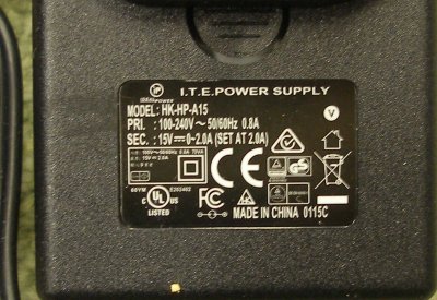
There are no details with the plug as to which one is suitable for the NCE Powercab. It is important to note that the 15 volt plug can be inserted into the 2-pin socket two ways, and the Powercvab won't work if it inserted the wrong way. The correct way is shown in the photograph below, with the white plug inserted, and with the '+' symbol aligned with the 'TIP' marking.
Running is now much better, with virtually all motive power units performing as they did using the Lenz compact. Of the three 'awkward' locos, one now runs in an acceptable fashion; one is OK so long as the wheels are very clean, but is marginal, and one remains a very slow (although beautifully so) runner. The two locos affected have Mashima-type motors using Branchline gearboxes, and will be side-lined for further investigation.
So the initial conclusion is that the NCE Powercab is a neat unit that is easy to install and use, but the UK-style plug with its 12 volt output should be avoided. UK users are recommended to either source the USA-type 13.8 volt power adaptor supplied by NCE, or buy the 15 volt power adaptor as supplied by Digitrains.
It is now nearly Christmas, and so further testing is going to have to wait to the New Year.
23 December 2015
First observations: (9 December 2015)
Early testing involved a range of ready-to-run models, notably a Hornby 'Britannia', Black 5 and 8F, together with a Hornby Class 101 DMU. Bachmann 108 and the Heljan Class 128 Parcels unit. These all ran well and smoothly. There was a small, but noticeable, reduction in top speed.
The second phase of testing involved kit-built locomotives, and it was apparent that locos with similar specifications were performing differently.
In summary, all locomotives ran more slowly than with the Lenz compact, and some ran very slowly indeed. About 20 percent of the fleet also ran erratically.
An e-mail to NCE support elicited that fact that CV29 probably needed adjusting. This is perceived as a complex CV to configure, and NCE recommended using the 2mm Scale Association's handy calculator. The specific problem is that 'Railcom' is not supported, and in the case of the 20% of the fleet performing erratically, this function was selected. In my case the value that needed to be written to CV29 was '6' (or if the loco needs to move in the opposite direction when 'Forward' is selected, the value should be '7').
This left the problem of the lower top speed. For the speedy RTR locos - designed to be more tolerant of a lower voltage - this was not a problem, but for the kitbuilt locos which already had lower gearing, it was a disaster, particularly for the express types.
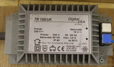
An examination of the Lenz compact showed that its transformer pack delivered 15 volts. The UK 13-Amp adapter plug was rated at 12 volts. The NCE support team had already revealed that the USA-pattern equivalent had an output voltage of 13.4 volts.
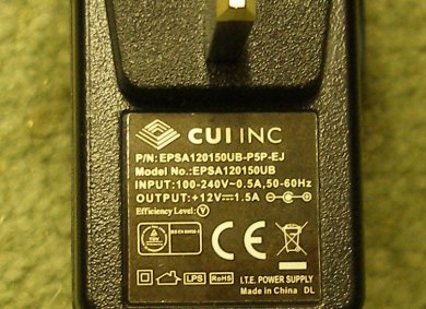
NCE offer a P114 Powercab Power Supply. This is described as "An additional or replacement DC power supply for the Power Cab system and other model railroad uses. Input 120VAC/220VAC, output 13.5VDC 2A peak. CE approved requires Shaver adaptor 2 to 3 pin". This retails at £21.82 from Digitrains.
A call to Digitrains confirmed that the observation was correct, in that the top speed was directly related to the voltage, and that a 20% drop in voltage had resulted in a fall in top speed of similar proportions. The problem appears to relate to difficulties in sourcing a UK-style adapter that delivers 13.8 volts, and it was suggested that most UK buyers would rather have a UK-style plug and accept the trade off in poorer performance.
Digitrains have kindly offered to swap the UK adapter plug for a US-style one, and after which further testing will be carried out.
9 December 2015
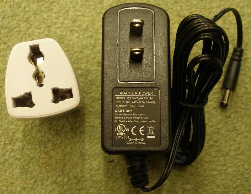
The Digitrains replacement US-style power adaptor has arrived...and was installed in seconds. Note the 13.8 volt output voltage.
In the beginning: 9 December 2015
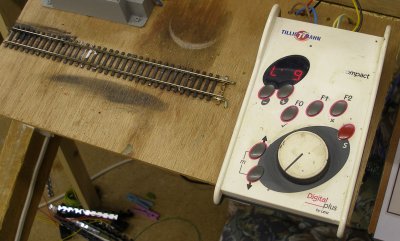
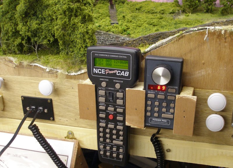
These notes relate to the NCE Powercab, which was selected in November 2015 as a replacement for a Lenz (starter) compact (illustrated below), together with the hand held Cab06, so that friends could drive a train as well. The NCE Powercab was selected for its apparent scability, as other systems require the wholesale replacement of components as the system grows.
Overview & Conclusion
The NCE system does what it says on the box. The lower-spec Powercab is adequate for a typical UK layout, and happily powers my 24' x 7' loft layout, with some 16 parallel tracks at its maximum.
It is very easy to install the upgrades (programming track auto-select, extra plug in points, etc). Programming is simplified. Selecting and programming accessories is also a simple set of commands. The design allows 16 macros to be programmed. These allow operation of multiple accessories with one button, allowing a number of signals and points to be thrown simultaneously, and so allowing route setting. The throttle design is easy to hold and operate.
Support from NCE is good, and there is an outstanding Yahoo! group (NCE-DCC) which has an authoritative membership that provides solutions to a very wide range of requests from radio throttles to rail joiner resistance.
There is an issue with the UK 13-amp plug-in power adaptor, and an alternative 15 volt UK adaptor is available from Digitrains. This is recommended.
Narrative
The NEC Powercab was superior to the Lenz compact in virtually all respects. The only small but significant detail is the 15 volt output of the Lenz unit.
Parts list:
The basic Powercab system consists of six basic items:
1. The NCE Powercab throttle
2. A 2-socket power panel (marked PCAB-PP)
3. A 13-amp Power Adapter (P114)
4. A 7 foot flat cable
5. A reference manual
6. A flexible cable - this is not required for the initial set-up and should be popped back in the box and stored.
A handheld cab 06 and a associated cable were also acquired with the aim of allowing friends to also operate the layout.
Set-up:
The manual has clear instructions on how to set up the system. A square hole needs to cut in the facia of the baseboard, into which the 2-socket power panel is inserted and screwed. On the back of this panel is a small pale green plug. This should be removed and two wires attached to it. This is the connection to the layout bus, where the two wires should be terminated. Once the wires are attached, the plug can be inserted into its socket. The power adapter now needs to be plugged into a mains socket, and the 12 volt jack into the socket on the back of the power panel. The red light on the front of the panel should now be illuminated.
Finally, the flat wire is inserted into one of the front sockets, and the other end into the base of the Powercab throttle. To complete the set-up, the cable supplied with the 06 cab is plugged into the handheld and the second socket on the power panel. With the mains socket switched on, the displays on both throttles should now be active.
The system is very easy to install, and experienced users will be running trains within 20 minutes of opening the box.
At this stage in the process, it was apparent that there was no-where to place the throttles. An internet search revealed that there are pockets made by NCE, and also various 'universal' throttle holders. I opted to construct two simple holders from off-cuts of wood, which took about 20 minutes to assemble.
There is no switching within the Powercab to allow a separate programming track, and as supplied, locos are programmed on the main layout, which means if there is more than one loco standing on the track, ALL locomotives will be programmed. One option is to fit a double pole double throw (DPDT) and wire one set of contacts to a separate track, so that either the main or the programming track is powered, but not both.
The NCE system uses the zero code for control purposes, which means that DC locos cannot be run on the layout using Loco code 0. As an aside, 'Powercom' is not supported either.
Specifics:
A curious omission with the manual is the lack of an index, although there are two Tables of Contents. This means that the manual has to be scanned each time there is a query. For instance, it was suggested that the Powercab might be in 'shunting mode'. It took a few minutes of scanning to discover that there was a reference to 'Yard mode', and that it is the larger Pro Cab that has the facility.
With the throttles active, it was possible to run the first loco. To select a loco press the 'Select Loco' button and dial the decoder number: '2' for '2'; and '12' for '12', and press 'Enter'. The liquid display shows the selected loco number, and the direction of travel. Scrolling the wheel, and the speed will be shown next to the direction. More locos can be dialled-up and set in motion.
There is a red 'Stop' button which has the advantage that it stops the locomotive rather than trigger the cut-out: however all other locos that are moving will continue to move.
This initial testing showed that the Gaugemaster relays used on the reversing loops to change the polarity were slower that the NCE cut-out, and so needed replacing before further testing could be carried out.
Copyright J K Wallace, t/a 'Hall Royd Junction' 2013-2023 email: Hall Royd Junction
7 Portobello Close, Chesham, Bucks. HP5 2PL, UK
tel: +44 (0)7513 412880