
<<< Switching copper-clad 4mm points Commissioning the Storage Yard >>>
Crossing the baseboard joint using PCB strip
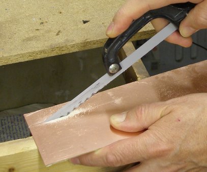
Photo 2
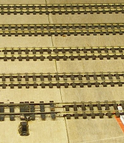
Photo 3
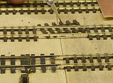
Photo 4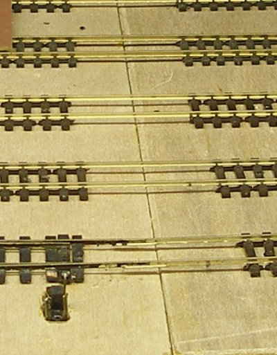
Photo 5
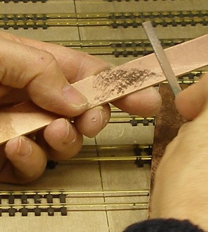
Photo 6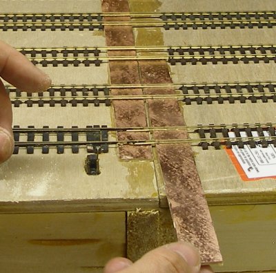
Photo 7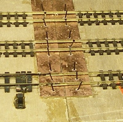
Photo 8
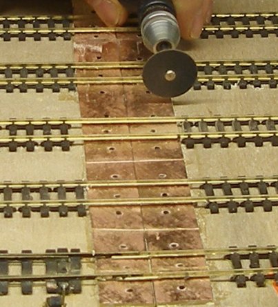
Photo 9
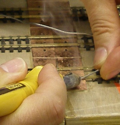
Photo 10
There are two ways of building a layout: either its a permanent feature with the benchwork firmly attached to the house, in the same manner of fitted cupboards, or the layout is designed to be taken apart so that it can be moved when a change of house occurs or even taken to exhibitions.
Hall Royd is of the latter type as I wanted to be able to bring baseboards down into the body of the house to be worked on. A house move is also a medium term prospect and the layout's predecessor lived in three different lofts.
Step 1 is to build and assemble the baseboards, and then lay the track over the join, with the track pinned in place, as shown in Photo 2. The storage yard uses Peco Code 70 with a mix of Peco and PCB points in the storage yard throat area. The end of each of the nine roads is then laid in Code 100 as I found I had a surprisingly large amount in good condition left over from previous layouts.
This section is in the throat area, so is Peco Code 70. It can be seen that the track nearest to the camera has a copperclad point to the left, and the first two sleepers were unsoldered from this to allow the continuous strip to be inserted.
I already had a sheet of copperclad fibreglass, and this can be bought from Internet resellers or eBay for around £3 a sheet or from Maplins. C&L also supply two depths of sleeper strip. Single sided copperclad fibreglass sheet is ideal for this purpose. If you need a thicker sheet, there is also double sided sheets available. However, if using double sided, do remember to gap the underside as well. Otherwise when you insert the nails/screws there will be a short circuit created via the bottom sheet. There is a comment to this effect on one of the model railway Web discussion groups.
In the old days it was copperclad paxolin but apparently fibreglass is a lot stronger. In the general scheme of things, I was expecting to score the copper layer and then snap in the manner of plasticard. Sadly the new material is indeed much stronger and it did score very easily. A cutting disc in a mini-drill produced a very irregular cut and was actually hard work!
Incidentally there are ready cut strips are available, with Marcway in Sheffied doing a variety of packs, and C&L doing O scale sleeper strips.
I concluded that a heavy duty hacksaw blade might be a better bet, and Wikes do a superior item costing twice the standard item. However, in fairness to all concerned, this did give a better cut, and having settled on 150 mm as the width of the strip, cutting started in earnest as see in Photo 1.
The item is described as a Wickes High Perfomance HSS steel hacksaw blade with 24 teeth per inch "offering a faster cut and superior durability". Code number 506033.
A section of the existing sleepers now needs to removed from the previously laid track. It is possible to cut through the sleeper web with a craft knife, and then slice off the rail chairs passing the craft knife blade sideways under the rail base, as shown in Photo 3.
Having done this, it is possible to tease out the section of sleepers.
Photo 4 shows the track with the sleeper webs removed.
Once all the sleeper strips have been removed, its time to fit the copperclad strips. Photo 5 shows it being lightly filed to roughen the surface to give a better purchase for the solder before fitting.
I used a combination of Bostick glue and track nails to firmly locate and fix the strips.
Photo 6 shows a thin coat of Bostick is applied to the baseboard top, and then to the bottom of the copperclad strip, which is then slid under the rails. Once in its final position and pressed down, a series of holes are drilled in the copperclad strips, into which are placed the track nails.
In Photo 7 the track nails are in the process of being hammered home, taking care not to distort the strip by hammering the nails too hard.
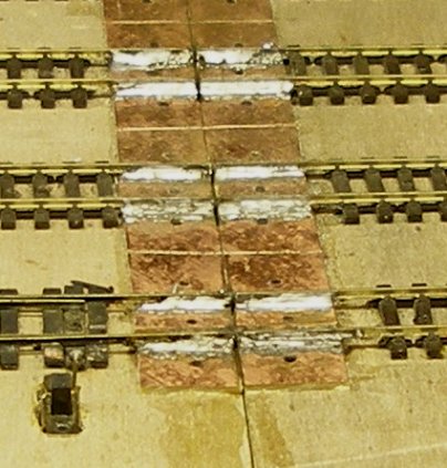
The copperclad strip now needs to be 'gapped' using a cutting disk and mini-drill, as seen in Photo 8. The copper cladding needs to be careful cut so that the underlying fibre glass shows through. There needs to be a cut between every rail, so that both rails of each track are isolated from each other and from the rail of the adjacent track.
Using multicore solder, each rail needs to be soldered along the section which is resting on the copperclad strip.
I lay the copperclad directly on the board, although I have seen it suggested that if there is a height discrepancy, a piece of card or similar can be inserted between the underside of the copperclad and the baseboard.
I am not keen on this, as I would rather have the copperclad firmly fixed to the board, without the risk of the packing material warping or distorting over time. I have tried both plasticard and card, and introduces a weakness at a key location.
Instead, where packing is needed I use either a section of bullhead rail on its side or copper shim from old frets (depending on the size of the gap) but ensuring it doesn't raise the height of the rail. This is placed between the rail and the copperclad, and then soldered in place.
Finally, the rails are cut along the line of the base board joint.
Some fettling may be required with a flat Swiss file or similar.
Solder
A comment on solder is required. I started with multicore solder bought from the local ironmongers. This worked quite well, but when I went back for more, they had run out and I had to use a cheaper, single core fluxed solder. This worked less well, and was almost like using a paste, not really flowing at all.
I therefore went back to my strategic stock of lead-based solder bought when C&L was telling people to buy now!
I regret to say that it melted beautifully and - used with lead-based flux - flowed beautifully. Of the three products used, it was the best by a long chalk.
However, all may not be lost, as my local Ironmonger DOES stock a lead-based solder on a roll, and it might be worth checking the traditional ironmongers or plumber's outlets.
A visit to Railex in Aylesbury on 24 May 2014 has provided a further selection of solutions, all using copper-clad fibre-glass in a variety of ways.
The Alloa lads have developed a copper fibreglass 'plate' which sits over the baseboard joint and is fish-plated to the rails at either end. It is then strategically screwed to the boards (Photo 11).
The second photo (Photo 12) shows the lines as they split into the running roads in the storage yards using a system very similar to Hall Royd.
The final shot (Photo 13) is of the Dewsbury storage yards and shows how simple these baseboard tracks can be. Notice how the track in the foreground has the copper-clad sleepers parallel to the baseboard joint, whilst the further one has the copper-clad sleepers laid conventionally (at right angles to the the rails) and then cut through with a cutting disc.
Posted 24 April 2014.
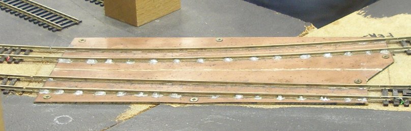
Photo 11: Alloa copper-clad fibre-glass placed over baseboard joint and screwed to board. Note fishplates for final alignment.
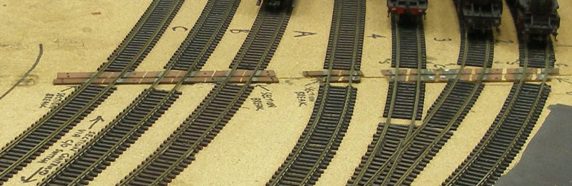
Photo 12: Alloa copper-clad fibre-glass strip nailed and glued to the baseboard. Looks almost identical to the Hall Royd arrangement.
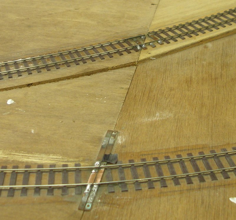
Photo 13: The MMRS 'Dewsbury' layout shows more variations on a theme, although here they are using conventional copper-clad fibre-glass sleepers. Hall Royd used to do it this way but had dimensional stability problems so needed something more robust. Clearly, its not what you do but how that you do it...
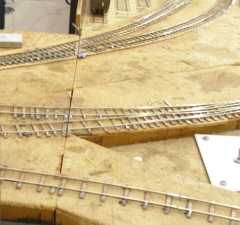
Photo 14: Shipley Model Railway Society's 'Leicester South' layout has its hand-made PCB sleepered track laid on cork underlay

Copyright J K Wallace, t/a 'Hall Royd Junction' 2013-2023 email: Hall Royd Junction
7 Portobello Close, Chesham, Bucks. HP5 2PL, UK
tel: +44 (0)7513 412880