<<< Connecting Code 70 track to Code 100 Crossing the baseboard joint using PCB strip >>>
Switching copper-clad (paxolin) 4mm scale points
using DPDT slider switches
Previously we looked at a method for switching points on the layout using a simple piano wire system described in BRM magazine. This was very cost effective, allowed the faster switching of points and also the resetting of the road after a train had run through when the points were set against it and shorted out the DCC control system - invaluable if there are points in tunnels.
Step 1: Drill a small hole in the slider switch big enough to take Gibson straight wire - the thicker the better.

Step 2: Drill a series of holes with a larger drill, to match the footprint of the switch.
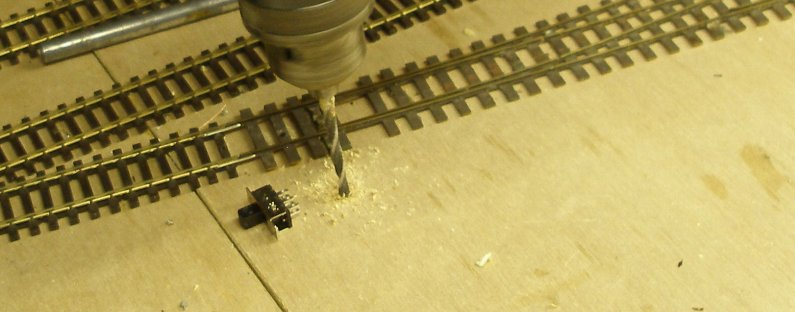
Step 3: Open out the holes using the drill like a router tool.

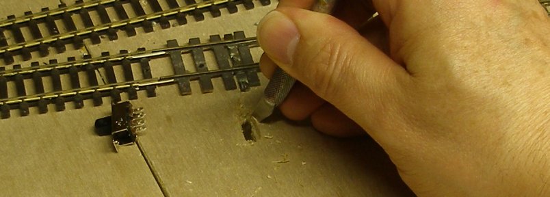
Step 4: Enlarge the hole with a craft knife until the switch is a push fit.
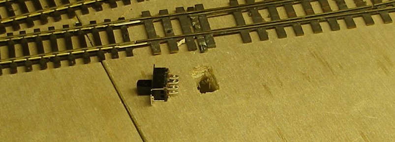
Step 5: The hole now fully opened out.
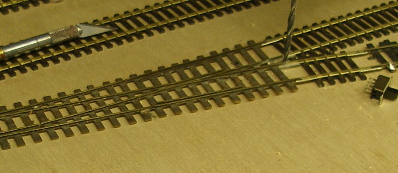
Step 6: Now drill three holes for the wires: one for the frog (illustrated) and one for each rail.
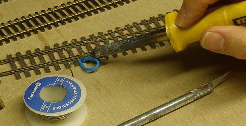
Step 7: Solder the wires to the three rails, and feed them through their respective holes. Don't do as I am doing here, and solder the wrong coloured wire to the rail. In my scheme of things this is the inner or 'brown' rail.
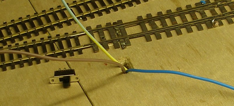
Step 8: The three wires are fed up through the hole cut for the switch.
Step 9: The three wires are soldered to the terminals on the switch. The wire from the frog goes to the centre tag.
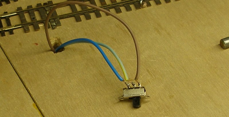
Step 10: The switch, with the wires attached, is placed back in the hole.
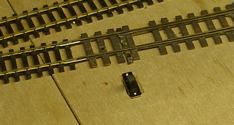
Step 11: A piece of the Gibson brass wire is bent and cut as shown, with the short end inserted into the hole drilled in the switch.
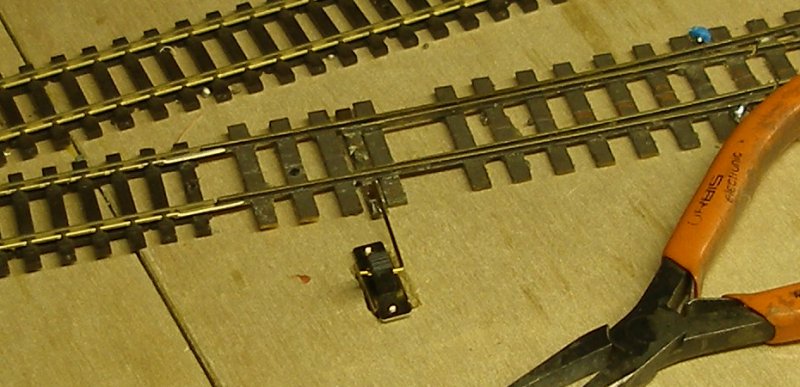
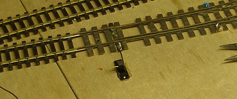
Step 12: The end of the operating wire is soldered to the tie bar. Job done.
All images copyright J K Wallace, c. 2013
Posted 1 April 2014
